


Fundamental processes in an induction lamp
2 Laboratory of Engineering Sciences and Applications, ENSAH, AbdelmalekEssaâdi University, Al Hoceima 32000, Morocco
3 Laboratory of Plasma and Energy Conversion (LAPLACE), University of Toulouse, CNRS, INPT, UPS, Toulouse, France
Received: 22-May-2023, Manuscript No. puljpam-23-6454; Editor assigned: 24-May-2023, Pre QC No. puljpam-23-6454 (PQ); Accepted Date: May 29, 2023; Reviewed: 26-May-2023 QC No. puljpam-23-6454 (Q); Revised: 27-May-2023, Manuscript No. puljpam-23-6454 (R); Published: 31-May-2023, DOI: 10.37532/2752-8081.23.7(3).204-209
Citation: Halima AB, Abdelmlak KB, Samoudi B, et al. Fundamental processes in an induction lamp. J Pure Appl Math. 2023:7(3);204-209.
This open-access article is distributed under the terms of the Creative Commons Attribution Non-Commercial License (CC BY-NC) (http://creativecommons.org/licenses/by-nc/4.0/), which permits reuse, distribution and reproduction of the article, provided that the original work is properly cited and the reuse is restricted to noncommercial purposes. For commercial reuse, contact reprints@pulsus.com
Abstract
This paper investigates the kinetic study in an inductive discharge lamp. Numerical simulation of electron density and other parameters that characterize the plasma are discussed and their values are compared with what is expected in inductive plasma and which show a good agreement considering the electron density and the electron temperature values. Such research allows us to understand the relationship between the radial distribution of electronic temperature and the electrical density of the lamp and the frequency of operation. The influence of the current is presented and the performance of the lamp can be found.
Keywords
Electrodeless lamp; Inductive discharge plasma; Magnetic field; Electron temperature; Electron density
Introduction
Electrodeless lamps (also called induction lamps) are already marketed by several major manufacturers thanks to many advantages such as reduction of the environmental load, energy saving since they are characterized by a long lifetime, low operating pressure and better color rendering [1,2]. In these lamps, no internal electrode in needed, so the problem of a weakness in the working electrodes is eliminated. They are able to produce a high plasma density even with a low gas discharge.
These lamps, functioning as fluorescent lamps, on the principle of a discharge in low-pressure mercury that activates a fluorescent powder, contain a quantity of mercury comparable to that of the current fluorescent lamps. They may operate from hundreds of kHz to tens of MHz [3-10].
This type of lamp uses an amalgam to control mercury vapor pressure [11, 12]. The bulb of the lamp (a closed quartz tube) is coated with a white phosphor. It is so important to understand the phenomena inside the plasma to achieve the high efficacy in these lamps.
Cold plasma is generated and maintained by radiofrequency electromagnetic fields. Understanding the fundamental mechanisms of the coupling of electromagnetic energy to the plasma and its transport to the walls is a major challenge for the control of industrial processes using cold radiofrequency plasma.
This type of lamps have been studied by many researchers such as Y Auira and J E. Lawler and have been carried out by [13,14], they use an experimental work to measure the ground level Hg atoms concentration and the ions density of the mercury. Other works were concentrated to find properties of such lamps with different mixtures [15]. Lister and Cox considered a constant electron density in order to study the electromagnetic equations [16]. Others experiments on induction lamp have been studied using different shapes of coils and taking into account the collision between electrons and atoms [17].
The success of numerical models (to help fluorescent compact lamp to have more efficiency) is limited by the lack of data available for the number of fundamental processes. This work provides some of this data using the numerical simulation.
Taking into account the principle of induction lamp, the geometry of the tube must ensure that the discharge is a complete loop. We have studied in our previous work the toroidal shape [18]. Now, we will study the plasma in a ring-type lamp.
Lamp Description
The schematic structure is given in Figure 1. The electrodeless fluorescent lamp uses an exterior ferrite cores closing around the discharge tube, that’s why these lamps have high efficiency due to their special coupling components [19,20]. The discharge contains Argon at a pressure of 300mtorr as a buffer gas and 6 mtorr of mercury. The frequency used in our simulation is 2 MHz and the applied current is 7.7A.

Figure 1: Schematic of the induction lamp and the meshing adopted in the simulation
Therefore, the numerical simulation of the plasma by the use of two modules which are coupled together was tried in this paper. The ferrite core produces the time varying magnetic field, (Figure 1).
Model Description
In order to model inductively coupled lamps, with the purpose of optimizing performance for maximum light output, a number of fundamental processes must be included. These processes include the depopulation of 63 P levels by the inelastic and super elastic collisions with electrons, or collisions with other excited atoms in the discharge (In these lamps, the elastic collision should play an important role in energy transfer into the plasma), also the radiation trapping of photons emitted from excited mercury atoms. These details are found more in our previous work [18].
Mathematical modeling of the ICP with COMSOL multiphysics involves coupling of the inductive plasma module and the magnetic module.
The equations of the plasma module
The plasma equations are solved in the drift-diffusion approximation and include a Collisional-Radiative model of the atomic electronic excited states.
The model adopts seven level for mercury. Argon is one of the simplest mechanisms to be implemented at low pressure discharge lamps. Thus, in addition to the Ar+ ion, the excited states can be reduced to a single excited level of argon in which the value of 11eV, 65 eV is the average value of the thresholds of the real levels weighted by their multiplicity. The reaction mechanism for Ar/Hg plasmas are found in our previous work [18].
In the model, the reactions, both of Argon and mercury, are based on fluid equations which are the electron density equation, the equation of conservation for heavy species (ions, neutral, excited) and the conservation equation of the electronic energy.
The continuity equation for the electron density:
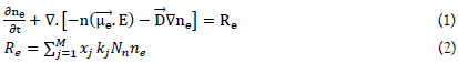
ne is the electron density (m-3), Re is the term sources for electrons (m-3s-1), Xj is the mole fraction of the species, kj is the rate coefficient (m3/s), Nn is the total neutral number density (1/m3),  is the drift of electrons in the local electric field vector
  is the tensor (to represent complex algebraic objects) of the electric mobility (m2 s-1V-1) and D = μeTe we use it for its ability.
The conservation equation of the electronic energy is:
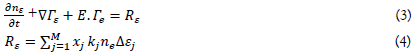
Te is the electron temperature (eV) which can be expressed as 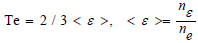 is the mean electron energy; nε is thedensity of the electronic energy (eV.m3). Γε is the electron energyflux, Γε is the Joule heating and Rε is the energy loss in collisionsand Δ represents the threshold energy.
The equation of conservation for non-electron species is:

ρ is the density of the gas mixture, wk is the mass fraction of the
heavy species, Rk is the term source term of the heavy species k and
Гk is the flow vector of the species k.
In this case, isotropy is considered. The tensor μe and D become scalars.
The equations of the electromagnetic field
The equations of the electromagnetic field are solved using Maxwell’s equation assuming an Ohm’s law closure relation as shown previously in [18].
Numerical Simulations
The equations system has been solved using the finite element method with Comsol multiphysics commercial software, this software offers a platform perfectly adapted to the development of coupled physical phenomena. The 3D numerical resolution of the fluid model transport equations is became possible thanks to the split-time step method which consists of replacing the three-dimensional transport equations by a succession of one-dimensional equations in each of the directions of the 3D geometry considered.
The meshing (as shown in Figure 1) is a critical step in any plasma model. The mesh used in the ICP model is chosen non-uniform triangular to respect as much as possible the physics of the problem, the mesh generation has been controlled in a way to refine the mesh in the vicinity of the coils to adapt numerically to the strong gradient of the electromagnetic field in these regions of the field of study. For the rest of the domain, we chose a size of increasing elements as we move away from the coils to reduce the calculation time.
The boundaries conditions are essentially in the reactions of surface which play an important role in the general characteristics of a discharge; this generally implies first-order reactions on surface where the excited or ionic species return to their ground state. (Ar+=>Ar, Ar(4s)=>Ar, Hg(63P0)=>Hg, Hg(63P1)=>Hg, Hg(63P2)=>Hg, Hg(61P1)=>Hg, Hg(73S1)=>Hg, Hg(63DJ)=>Hg, Hg+=>Hg). The gas temperature is about 350K in the volume of the discharge.
The conditions on the walls are:
• no voltage (V=0);
• the thermal emission flux (Гt) is set to zero,
• The ion flux (Γi) is set to zero,
• The mean thermionic energy of electron (ε) is set to zero as demonstrated in Eq. (6) and (7).
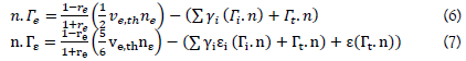
Here: re is the reflection coefficient, it is usually zero
Ve,th is the thermal velocity of the electron,
γi is the secondary electron emission coefficient
εi is the mean energy of the secondary electron emission.
Results and Discussion
Now we will discuss that the results obtained in order to better understand the operation of the discharge.
Figure 2 shows the distribution of the magnetic field in the lamp, it is clear that the magnetic field is intense in the ferrites and its lines are confined in this area as shown. The variations of the electromagnetic field propagate in the space in the form of waves then the intensity of the field decreases when the distance increases from the volume r that contains the ferromagnetic materials.

Figure 2: Streamlines of the magnetic field and its distribution
The electron density in the plasma core region attains its maximum value (about 1018m-3) which is typical in a low pressure electrodeless lamp and which shows a good agreement with previous works [15- 18].
The density of electrons is higher in the center, but at the level of the walls it decreases gradually, and this is because of the diffusion of ions and electrons in these regions. The charged species are concentrated in the induction zone, which has the most reactive medium of the plasma (Figures 3,4).

Figure 3: Distribution of the electron density (1/m3)

Figure 4: Distribution of the electron temperature (eV)
This figure shows clearly that the maximum electron temperature is at the induction turns. It gradually increases from the coil area to reach a maximum of 1.62 eV. This shows that the induction zone is indeed the zone of high energy density. Indeed, this magnitude must be higher just opposite the coils where the dissipated power density is almost maximum as shown in Figure 5 , 6. When moving away from this area, the electrons cool considerably (about 0.6 eV). Also the deposited power can be explained by the current density in Figure 7.

Figure 5: The power deposition in the lamp (W/m3)

Figure 6: Distribution of the electrical potential (V)

Figure 7: Distribution of the Current density inside the lamp (A/m2)
The electric energy is mainly transferred to the electrons, which become the hot species of the discharge, these passed a short distance before changing direction, this implies that few electrons reach the surface during a cycle thus minimizing the load effects, so the surface has a potential which is equal to zero and a maximum value in the center as shown in Figure 6.
Due to the variations of the electric and magnetic field, the majority of the power is close to the coils as shown in Figure 5, inside, this power becomes negligible, that is why the current density is intense in this region as shown in the Figure 7, (The peak of dissipated power is greater than 3 *108 (W/cm3). These two figures 5 and 7 show that the power is transferred from the electric field to the plasma inside a layer of depth of skin of thickness of scale length γ, generally the electromagnetic wave cannot penetrate into the plasma at high level of density of more than a few skin depths which is in our case 3 mm.
The skin effect is an electromagnetic phenomenon which causes the current at high frequency to circulate only on the surface of the conductors. This phenomenon of electromagnetic origin excites for all the conductors traversed by an alternating current. Decreasing the density of the current as one move away from the driver's device, these results in an increase in the resistance of the conductor (Figure 8).

Figure 8: Density of ground state of mercury Hg (1/m3)
In the discharge, the density of electrons and ions is high in the center of the discharge, in fact, there is no excitation and ionization of the ground state in the wall but inside the discharge there is enough energy to excite and ionize the gas therefore according to Dalton's law, this leads to the reduction of the density of the first state of the mercury since the total density of the mercury is equal to the sum of those of the ions and mercury gas (Figures 9,10).

Figure 9: Distribution of ion mercury (1/m^3)

Figure 10: Distribution of the electron density as function of current
The influence of the current on the behavior of the lamp
The electron density in figure 10 increases with the current, because the role of collisions between the mercury atoms with electrons increases.
Figure 11 shows the dependence of the electric field intensity in different currents. It reaches the maximum in the region of copper coils, in fact, the mercury atoms density increases, which causes the mean free path of electrons to reduce. Therefore, the electron temperature falls and the electron mobility μ decreases. But the density of ground state mercury atoms increases at the same time. So, there is a minimum of electron density and a maximum of electron drift velocity μE, which makes the electric field intensity increase first in the periphery and decreases inside the coils. The electric field intensity becomes saturated in large current. It may be resulted from mercury depletion as shown in Figure 12(average value at a point near the coils), which takes place in the very thin where the ambipolar diffusion was promoted [18].

Figure 11: Plot of the Electric field in function of different values of current

Figure 12: Density of mercury in function of different values of current
Argon will become main species to sustain discharge after mercury is depleted. As the ionization potential of argon is higher than that of mercury, the electron temperature will decrease. Then the electric field intensity increases, counteracting the decrease caused by high cold spot temperature (Figure 12).
It’s also indicated in figure 12 that the electric field intensity falls with increasing current.
Conclusion
A 3D simulation method has been used to investigate the physics of ICP in a mixture of Argon and mercury working at a frequency of 2 MHz and a current of 7.7 A. Two modules are coupled together to obtain a better understanding of an ICP. The calculation of the charged densities, the electron temperature and the electric field were presented in this paper.
The different results obtained by the simulation show the capacity of the numerical method used for the model to describe the main phenomena that occur within this type of electric discharge since the search for the characteristic of the plasma has been little reported ad that shows that discharge is spreading.
Ethical Approval
Applicable for human studies.
Competing Interests
The authors declare that they have no competing financial interests or personal relationships that could appeared to influence the work reported in this paper.
Authors' Contributions
All authors have made substantive contribution to this study and have reviewed the paper prior to its submission.
Funding
Not applicable
Availability of Data and Materials
Not applicable.
References
- Wilschefski SC, Baxter MR. Inductively Coupled Plasma Mass Spectrometry: Introduction to Analytical Aspects. Clin Biochem Rev. 2019:40(3);115-33.
- Godyak VA. Radio Frequency Light Sources. Ind Appl. 5(3):3281-88;2000.
- Czerwiec T. and Graves D B 2004 Journal of Physics, 37 2827-40. [Google Scholar] [Crossref]
- Hewitt PC. Method of producing electric light. 1907.
- Anderson JM. Electrodeless gaseous electric discharge device utilizing ferrite cores. 1970.
- Bogaerts A, Neyts E, Gijbels R, et al. Gas discharge plasmas and their applications. Spectrochim Acta B: At Spectrosc. 2002:57(4, 5); 609-58.
- Yuan H, Gojani A, Gornushkin I, et al. Investigation of laser-induced plasma at varying pressure and laser focusing. Spectrochim Acta B: At Spectrosc. 2018:150;33-7.
- Kido H, Makimura S, Masumoto S. A study of electronic ballast for electrodeless fluorescent lamps with dimming capabilities. In Proc Conf Rec IEEE. 2001:2;889-94.
- Miyazaki H, Shoji H, Namura Y. High-frequency class-D converter driving with feedback capacitors for electrodeless fluorescent lamps. IEEE Trans Ind Electron. 2000:36(4);1033-38.
- Jang TE, Kim HJ, Kim H. Dimming control characteristics of electrodeless fluorescent lamps. IEEE Trans Ind Electron. 2009:56(1);93-100.
- Atrey P, Pujara D, Mukherjee S, et al. Design, Development, and Operation of Seven Channels’ 100-GHz Interferometer for Plasma Density Measurement. IEEE Trans Plasma Sci. 2019:47(2);1316-21.
- Liu Y, Zissis G, Chen Y. 2011 J. Phys. D: Appl. Phys. 44 305201. [Google Scholar] [Crossref]
- Lister GG, Curry JJ, Lawler JE. 2004 J. Phys. D: Appl. Phys. 37 3099. [Google Scholar] [Crossref]
- Nerone LR. A novel ballast for electrodeless fluorescent lamps. In Proc IEEE Appl Power Electron Conf. 2000:3330-37.
- Kornev RA, Gornushkin IB, Nazarov VV, et al. Features of hydrogen reduction of SiF4 in ICP plasma. J Electrost. 2022:1985;106502. [Google Scholar] [Crossref]
- Han QY, Zhang SD. Strong lines emitted from positive column of narrow bore T2 low-pressure Ar–Hg discharges. Appl Mech Mater. 2013:325-326;405-08.
- Chung Y, Jung DC, Kim YK, et al. Study of the Characteristic and Optimization of Induction Lamp according to Gas Pressure and Amalgam Type. J Korea Inst Inf Electron Commun Technol. 2017:10(1);23-30.
- Halima AB, Hajji S, Barkaoui G, et al. Numerical Simulation of Plasma Kinetics in a Low-Pressure Inductively Coupled Discharge in Argon and Mercury Mixtures. IEEE trans plasma sci. 2018:47(1);162-72.
- Lister GG, Cox M. Modelling of inductively coupled discharges with internal and external coils. Plasma Sources Sci Technol. 1992:1(1);67.
- Godyak V. Plasma phenomena in inductive discharges. Plasma Phys Control Fusion. 2003:45(12);399.