

Supercomplex network of bistable coiled vortex filaments and ribbons in laser-matter interactions
Received: 01-May-2018 Accepted Date: May 15, 2018; Published: 22-May-2018
Citation: Lugomer S. Fukumoto Y. Supercomplex network of bistable coiled vortex filaments and ribbons in laser-matter interactions. J Mod Appl Phys. 2018;2(2):1-9.
This open-access article is distributed under the terms of the Creative Commons Attribution Non-Commercial License (CC BY-NC) (http://creativecommons.org/licenses/by-nc/4.0/), which permits reuse, distribution and reproduction of the article, provided that the original work is properly cited and the reuse is restricted to noncommercial purposes. For commercial reuse, contact reprints@pulsus.com
Abstract
We study variation of patterns formed by multi-pulse laser-matter interactions when the number N of pulses is increased. Variation of N causes formation of vortex filament bundles, thick filaments, ribbons, and tubular-ribbons. Their straight and the angular bistable coiling are caused by a double-valley twisting potential emerging from the Landau-Ginzburg twisting potential. In addition, such a coiling undergoes a conformational change brought by propagation of a Davidov’s-like soliton. These structures called “complexes” become interconnected into a network on a 2D lattice. Further increase of N induces a 3D supercomplex network. For N greater than a certain critical value, the organizational pattern breaks down into simpler structures.
Keywords
Laser-matter interactions; Nonlinear fluid flow; Vortex filaments; Vortex ribbon; Ribbon-helicoid; Tubular-ribbon helicoid; screw helicoid; Bistable coiling; Complex network
Introduction
Generation of coherent filamentary and ribbon structures with space-time localization of characteristic physical properties is a general phenomenon in dynamical systems in accelerated flow environments [1,2]. The appearance of such coherent structures spans from atomic to nano-and micro-scales, and extends up to astrophysical-scale as a result of nonlinear dynamics [2,3]. Examples are vortex filaments and ribbons in Bose–Einstein condensates, superconductors and super fluids [4-6], the magnetic flux tubes and cosmic strings [2,7], and also vortex filaments and ribbons in the shear layers on condensed matter surface generated by laser-matter interaction (LMI) [8-11]. Filamentary and ribbon structures exhibit, in some cases, coiling and supercoiling [12,13], and, in other cases, knotted [14]. Coiling and bistable coiling of filaments and ribbons which generate helices on metals, semiconductors and piezoelectric materials are important for application in optics and opto-electronics etc. in the nanotechnology evolution. Depending on the conditions, a diversity of structural conformations are organized, which ranges from random to complex (architecture) patterns as observed on silicon [15] and on the semiconducting oxides of Zn, Sn, In, Cd, and Ga [16,17]. Very complex organization of ZnO ribbon coils [18], NbSe2 ribbons [19], TiO2 ribbon coils [20] and carbon micro-and nano-coils [21- 24], represent modern research topics in the material science.
Regarding LMI, the question is whether filaments and ribbons generated on the surface shear-layer form coils, bistable coils and helices, and whether these structures may eventually be organized into specific patterns. The study is based on the fact that vortex-filament arrays embedded in structure less background fluid are evolved by irradiating a few pulses. Continuation of irradiating pulses causes the onset of inhomogeneous turbulence and interaction of the filament array with localized strain fields. The strain fields can be (quasi-)static or oscillatory, whereby torsional and twisting filamentary structures appear at scales ranging from nanometers, typically tens or hundreds of microns to millimeter scale. With increasing N, the filaments are collected into bundles, thick filaments, ribbons and tubular ribbons. Our hypothesis was that their interaction with localized strain fields gives rise to patterns, with its complexity being controlled by the number N of pulses and the density of vortex filament array. To test the hypothesis, the comparative study is performed on two kinds of arrays of vortex filaments, the lowdensity and on the high-density filament arrays. We show that interaction of filaments and ribbons in these two arrays with localized strain fields generates helicoids, bistable-coiled filament helicoids, ribbons and tubular-ribbon helicoids. These structures develop patterns ranging from a simple random pattern (in the low density array) to the layered interconnected supercomplex network formed in a multi-stage organizational process (in the high density array). Formation of patterns and their variation in these arrays was studied as function of the number of pulses N. We follow the organizational process in which bundles, thick-filaments, ribbons, and tubular-ribbons, with increase of N, become transformed into coiled, helically coiled, bistable coiled filaments and ribbon-helicoids structures. These structures, which may be termed as complexes (in the high density array) become interconnected and organized into a network. In a usual sense, a network represents a stable association which exhibits some organizational regularity on the lattice, or the organizational concept, and may be architecture of many «complexes» as building blocks. Such organization (architecture) of filaments and ribbons generated, depending on some external control parameter, by the localized (sub-) micron static and dynamic fields (domains) as the interaction environment is of common occurrence of physical [25], chemical and biological [26] systems and cover research topics in various scientific areas. Among them are static domains of the electric field (defects in crystals) which trap filaments and ribbons of magnetic flux in superconductors [25]. Domains of the baroclinic field trap the filaments of material growing in the vaporization chamber like silicon and carbon nanotubes, depending on the frequency of repetitive forcing of some external agent. However, dynamic domains interact with metal wires, belts and nanotubes of Si and Ge [15] in a reaction environment to produce their coiling and bistable coiling. Well known examples are the twisting domains that form carbon nanocoils by chemical vapor deposition (CVD) in the catalytic pyrolysis of acetylene, depending on the electromagnetic wave emitted from the heater [20,22,27,28]. Coiling-formed carbon tubes in 2D and 3D with changing-chirality, zig-zag-formed carbon nano-fibers as well as ropes were obtained by using localized catalyst particles in a reaction environment [23]. The change of the coiling-chirality during the process of chemical reaction was mainly caused by the gradual variation in chemical composition present on the surface of the catalyst grains (localized fields). This list can be completed by localized biochemical fields in biopolymer solutions connected with the ionic electric field that causes coiling or bistable coiling of the organic polymers [29-31]. Common to all systems is that coiled and bistable coiled filaments and ribbons, the complexes, tend to become organized into patterns in such a way as the complexity level increases with increasing the external control parameter. At the critical value of the control parameter, the conformation reaches an organizational slimit, accompanied by a catastrophic change of organization into a lower complexity level [11]. Similarly, in the multi-pulse laser experiments, the strain forces exceed, at the critical of N, the elasticity limit of filaments and ribbons, causing disintegration of the supercomplex network into structureless chaotic pattern.
Outline of Experiment
Small samples of Co-coated steel of 1 × 1 × 0.05 cm were exposed to the focused Gaussian beam of XeCl excimer laser (λ=308 nm), of E 300mJ, and of the pulse duration of t ∼ 20ns. Irradiation of the sample perpendicularly from above generated a molten surface layer with characteristic gradients of pressure and temperature. The multi-pulse interaction was performed at the repetition frequency of 2Hz. The vertical thermal gradient ∇T⊥ raises the top surface layer to the boiling temperature Tb, while the lower surface layer is at the melting temperature, Tm. This causes the formation of the shear layer which is accelerated by the Rayleigh-Taylor instability from the center to the periphery of the spot. The top layer of low-density and high temperature is moving faster than the bottom one. Any vertical perturbation of the shear layer, like vertical oscillation, causes the formation of breaking waves. When the Reynolds number Re of accelerated fluid reaches the critical value of Re ∼ 103, the Kelvin-Helmholtz (KH) instability sets in, causing transformation of the breaking wave into the roll up process which generates vortex filaments [11].
The vertical oscillation of the accelerated shear layer can be induced by parallel micron-and submicron scratches made on otherwise a smooth surface of Co-coated steel. The scratched defects promote the KH instability with inducing formation of micron-scale vortex rolls. The roll-up process is triggered by the scratches extending, say, in the radial directions on the target surface. An oscillatory shock perturbs the density interface (shear layer) transversally to the radial flow, or the flow from the central to the peripheral regions, causing the formation of waves and their roll-up into vortex filaments. The perturbation amplitude is equivalent to the height of the scratch wall, while the perturbation wave vector is inversely proportional to the distance between the scratches. Once formed, vortex filaments enter the formation of various structures with increasing number of pulses. The oscillatory strain fields cause the transformation of vortex filaments and ribbons into “complexes”, organized patterns, the topological complexity of which depends on the filament-filament separation distance, and on the number of pulses.
In order to cause the formation of even more complex structures, the surface scratches of different length and different density were made-in contrast to the previous case of parallel equidistant scratches of the same length [11]. The scratches were also of different depth, varying between the nm to μm and to the tens of μm. Thus, the high as well as the low-density scratch arrays were formed in various regions of the target surface. Such surface patterning caused the formation of a series of the shock waves with different wave-vectors, phase, and intensity. Diffraction of the shock wave at the ends of short filaments and additional perturbation of the shear layer generate inhomogeneous strain field. The collided and reflected shock waves cause the formation of a number of circulating and counter-circulating micronscale domains with localized shear field characteristics. The interaction of filaments and ribbons with these strain fields generates various complex structures in different regions of the target.
The structures become organized into permanently frozen patterns due to ultrafast cooling immediately after pulse termination, thus making possible a posteriori analysis. The frozen surface structures have been studied by the Nikon optical microscope and registered by CCD camera. The best pictures of the surface structures were obtained by tilting the table of the microscope. Only a slight tilting is needed to get the view-angle with the depth of the observed object(s). If the tilting angle is too large, the objects become dark and actually cannot be observed. The optimization of the view-angle was performed for every new sample or analyzed spot by repeated adjustment of tilting. Further optimization of the picture is obtained by the variation of color which illuminates the sample (by the change of the optical filters), as well as by the variation of the illumination intensity.
Results and Discussion
Characteristics of the interaction space
Regarding the LMI the question is whether the interaction medium can be taken as isotropic or not. The polarization presented as a power series in the field is [32-34]:
P = ε0 (Χ(1)E + Χ(2)E2 + Χ(3)E3 + …) E (1)
Where Χ(1) is the linear electric susceptibility and Χ(2) and Χ(3) are second-and third-order nonlinear optical susceptibilities, respectively. The laser power is relatively modest, and the E field is low. Since the second order susceptibility Χ(2) for condensed matter is of the order of [32]:
Χ(2) ∼1.94 x 10⁻¹² m/V, (2)
and especially for metals Ag, Cu, Al and Ta is of the same or even lower value, the higher order effects can be neglected. For simplicity, a scalar formalism is kept throughout the text, corresponding to a linearly polarized field in an isotropic medium. Thus, the linear refractive index of target (Cobalt layer) according to Johnson and Christy [35] for the XeCl laser wavelength (λ ∼0.308 μm) is: n ∼ 2.1396.
Evolution of primary and secondary coherent structures: The characteristic of LMI is that first few laser pulses cause the formation of an array of parallel vortex filaments of different length and of variable filament-filament distance in the interaction space (Figure 1a). Two arrays of parallel vortex filaments have been formed: A low-density array with the filament-filament distance ˄1˃˃ σ where σ is the filament core thickness (σ 5-7 μm), has been developed in the left-side region of the target surface. A high-density filament array with the filament-filament distance ˄2 ≲ σ, has been generated in the right-side region. Vortex filaments in both arrays represent the primary coherent structures.

Figure 1) 1. Schematic illustration of vortex filament formation in the structure less background fluid at the target surface, with increasing number of ulses, N. (a) Formation of vortex filament arrays (primary structures) on the scratched surface (surface patterning); (i) After few pulses, a low density filament array with the filament- filament distance ˄˃˃ σ is formed at the left side and the set of high density arrays at the right side. The distance between the arrays is ˄1˃˃ σ while the filament – filament distance inside every array is ˄2 ≲ σ (σ is the filament core size);
(i) By increasing N to about N ~ 10, a low density filament array does not change much (left side), while in the high density array, the filaments come close to each other forming bundles, thick filaments, ribbons, and tubular ribbons (secondary structures). (b) Transition from homogeneous into inhomogeneous turbulence with increasing N causes (i) the formation of localized strain fields in the shear layer;
(ii) Localized strain fields generated inside the array of bundles, thick filaments, and ribbons. Localized (quasi-)static field (rose color), and the field of counter circulating fluid.
In the low density array, the increasing number of pulses causes that filaments tend to take position in the minimum of the oscillatory strain field, staying at the position ˄1˃˃ σ (Figure 1a(i) left).
In the high density array, under oscillatory strain field, the filament-filament distance ˄2 ≲ σ is practically regarded as zero.
In this isotropic medium, the closely spaced filaments come closer giving rise to a 1D array of bundles, of thick filaments, ribbons, and of tubular-ribbons as the secondary coherent structures (Figure 1a(ii) right).
Filament bundles: Under oscillatory strain field, filaments start to aggregate in the regions of the minimum strain. If lateral (parallel to the surface) and vertical (normal) strain field components are comparable, the filaments move closer and form a bundle.
Thick-filaments: Under subsequent pulses, a bundle of filaments experiences growing compression. The compression invites resistance to the filament motion and causes their axial merging. The approaching filament longitudinally stretches and its cross section narrows. As the angular momentum is conserved, the vortex filament spins faster enhancing the co-rotation of the same signed filamentary vortices and intensifying viscous diffusion. The crucial role in axial merging play the viscous diffusion term, a source term due to stretching, but also an advection term with variable advection speed. Consequently, the compressed bundle becomes transformed into a thick-filament.
Ribbons: If the lateral compression caused by the oscillatory strain is larger than the normal one, it induces their axial merging into ribbons. The longer axes of flattened filaments are parallel to the surface and lie inside the shear layer [11]. The stationary strain wave drives the ribbons (formed by N ≳ 10 pulses) into the regions of minimum compression (between two maxima). Once they become close to each other, the vertical component starts to increase to form ribbons into the vertical position to the surface [11].
Thus, a 1D array of bundles, of thick filaments, of ribbons and tubular-ribbons as the secondary structures evolves in the high density filament region, as schematically shown in Figure 1a(ii) right.
Evolution of localized strain fields: Another characteristic of LMI is that first few laser pulses cause the formation of the strain field on the molten surface layer in the interaction space. By increasing the number of pulses, the strain field becomes modified and decomposed into localized static and dynamic fields (strain domains) (Figure 1b(i) and b(ii)). Localized (quasi-) static fields have the strain gradient oriented from the circumference towards the center, and may cause pinning of filaments and ribbons. The trapping potential and 2D projected map of the pinning center (Figure 2a), are similar to that of the real point defect.
Besides (quasi-)static strain fields, the dynamic localized fields of fluid oscillation, circulation, and counter-circulation are generated by the train of laser pulses. The domain of the counter-circulating fluid (vertically segmented by the cross sections of the shear layer), shows the sequential change of the local vorticity (Figure 2b(i)). Its orthogonal projection onto the upper horizontal plane shows a 2D map with subdomains of the left-handed (red), and the right-handed circulation (blue) (Figure 2b(ii)). The intensity of colored contours changes from the periphery to the center of subdomain and represents the strength of the localized field. The corresponding 1D picture of these subdomains is a double valley twisting potential (Figure 2b(iii)). In the multipulse LMI the vortex filaments as primary coherent structures in the low density array interact with localized strain fields giving rise to various structures and patterns-different from the structures and patterns generated by the interaction of the secondary coherent structures with localized strain fields in the high density array.

Figure 2) Characteristics of localized strain fields. (a) Localized (quasi-)static strain field has characteristic of the trapping center and may be represented by the potential valley, similar to the pinning center of the real point surface defect. (c) Localized field of fluid counter circulation; to the left (red), and to the right side (blue).
(i) A local shear-layer domain with the fluid counter circulations.
(ii) A domain segmented by vertical cross- sections showing the local vorticity and the corresponding 2D map which is orthogonal projection of the field of counter circulating fluid.
(iii) The counter circulating field with 2D projected map and with corresponding double-valley twisting potential.
Low density array
Formation of random pattern of bistable coiled helicoids: In the low density array of vortex filaments (Figure 1a left), the interaction of parallel vortex filaments as the primary coherent structures with localized strain fields for the number of pulses N ≥ 15, leads to the formation a random pattern of bistable coiled filaments (Figure 3). Such pattern is the result of interaction of individual vortex filaments with a double valley twisting potential (Figure 2b). Schematic illustration shows a filament in the vicinity of the opposite twisting strain field (Figure 4a), the initiation of bistable coiling (Figure 4b) and bistable coiled filament with segments of the left-and the right-helicity separated by the inversion point (Figure 4c).

Figure 3) Optical micrograph showing a random pattern of straight and angular bistable coiled filaments, formed in the low density filament array after N ≳ 15 pulses.

Figure 4) Interaction of vortex filament with localized strain field of counter circulating fluid. (a) Vortex filament in the vicinity of counter- circulation fluid is exposed to its strain field. (b) The strain field causes bending of filament and the beginning of bistable coiling (c). Bistable coiled filament comprises segments with the left and the right side helicity separated by the inflection point (C). Schematically.
Description of straight and angular bistable coiling with the change of radius etc., in the field of laser-matter interactions requires identification of the equations and models which are basically nonlinear. Definition of models, algorithms and solution of differential equations, numerical simulation by different methods is a challenging problem. It was found that an effective tool to describe physical phenomena like fluid flow, elasticity.., but also biological ones… etc., are fractional partial differential equations (PDEs). They are a type of differential equation involving unknown multivariable functions and their fractional-integer partial derivatives with respect to those variables [36]. A great effort is recently done especially in building fractional mathematical models for specific phenomena and developing methods for solution for PDEs [37,38], including nonlinear fractional KdV-Burgers equation for shallow water system [39].
Regarding a thin (shallow) fluid layer generated by LMI and bistable coiling of filaments we assume-as the first approach-that the Landau-Ginzburg twisting potential [which describes bistable coiling of the elastic bacterial filaments from the small scale ∼ 15-25 μm [40] to the very large macroscopic botanical filaments ranging from millimeter to centimeter scale [41], can also describe bistable coiling of elastic vortex filaments of ∼ 40-80 μm in length observed in this experiment.
Straight bistable coiling: The micrograph in Figure 5a shows straight bistable coiled cobalt filament which is free at both ends. The change of the helix chirality is caused by the opposite twisting of the filament without external constraints. In spite of this, comparison can be made with the bistable coiled filament (Figure 5b) of Goriely and Tabor [41,42] which was fixed at both ends, and whose chirality was supplied by the external constraint. The change in chirality is displayed on a circle (Figure 5c) in the parameter space defined by τ (torsion) and (curvature) K. In the case shown in Figure 5c, τ ranges between 0 and ± 0.15, while K ranges from 0 to ¼ [41,42]. The straight bistable coiling occurs when the twist front propagates along the straight filament (α=1800) between two minima Tw±, of a symmetric twist potential V0 (Tw) when ΔTw=0.

Figure 5) Straight bistable helical coiling (α = 1800). (a) Optical micrograph clearly shows the inversion point.(b) Sketch of a helix reversal. (c) The optimal solution curves in the τ-K plane together with the two optimal helices (circles) obtained for K=¼, Γ = ¾. n=1/8. (Courtesy of A. Goriely; Reprinted with permission Figure 2 from A. Goriely and M. Tabor, Phys. Rev. Lett, 80 1564 (1998). Copyright (1998) by the American Physical Society.
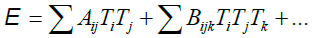
Angular bistable coiling of filaments: Figure 6a(i)-a(iii) show increasing number of coils which occurs if vortex filament interacts with localized strain field represented by a double valley twisting potential (Figure 6b(i)). The dynamics of the filament could be described by the model of Goldstein et al., [40] based on the intrinsic curvature and twist of thick filament. In this model, angular bistable coiling with angle 00 < α <1800 is caused by the strain tensor T acting on an elastic filament. The model is constituted as building block, by an orthonormal set of vectors, {e1,e2,e3}, where e3 is the tangent vector, e1 points from the centerline to the rod surface along a specific direction, and e2=e3 × e1. A segment of the curved filament around a point specified by the parameter s is exposed to a strain vector T(s)= (T1,T2,T3), which bends the filament, endowing it with curvature. This strain vector shapes the filament through the kinematic relation ∂sei=T × ei, (i=1,2,3), and the curvature K satisfies K2=T12+T22, with T3 being the twisting angle per unit length. The elastic energy of the filament, E[T] is described by the Landau expression [40]

Figure 6) Angular bistable helical coiling. (a) Optical micrograph showing bistable coiling of vortex filament. (α ~ 350). Optical micrograph showing (i) early phase of bistable coiling; (ii) intermediate phase of bistable coiling and (iii) the late phase of bistable coiling. (b) Bistable helical coiling along two directions under an angle.
(i) The asymmetric double-valley potential in the twist variable;
(ii) The elementary front solution of the twist;
(iii) The double helix cores-ponding to Figure 2A (Courtesy of R.E. Goldstein; Reprinted with permission Figure 2 from R.E. Goldstein, A. Goriely, G. Huber and C.W. Wolgemuth, Phys. Rev. Lett, 84 1631 (2000). Copyright (2000) by the American Physical Society.
 (3)
(3)
With symmetry conditions imposed on the allowable elastic constants Aij and Bijk. Minimizing the elastic energy, (3) with identification T3 ≡ Tw (twist) gives the helix as a ground state or the minima of the sum of curvature and the twist energy. For a thin elastic filament or a rod, (3) simplifies to [40]
 (4)
(4)
Where A is the bending stiffness and C is torsional rigidity. A helical filamentary conformation appears as the ground state if the minima of both, the curvature and the twist energy are shifted from zero to intrinsic curvatures T10 and T20, and intrinsic twist Tw0 [40]. Then, the simplest thin filament model for a bistable helix, featured by curvature and two stable twist states, gets the following expression for the Landau-Ginzburg functional for the energy in terms of the twist strains [40]
 (5)
(5)
Where ΔTi=Ti–Ti0 (i=1,2) and V(Tw) is a double-well potential (Figure 6b(i)). In this case, the twist-gradient coefficient γ controls the width of fronts connecting the two states (Figure 6b(ii)). The most intriguing pattern of such fronts is a filament comprising two helices of opposite sense connected at an angle α, being referred to as a bistable helix, as schematically shown in Figure 6b(iii).
The two energy minima of the above functional correspond to the two stable twist states of bistable helix. Continuity of the tangents at the junction of the two axes determines the «block angle» α to be
 (6)
(6)
Where K± and τ± are the curvature and torsion of the two helices, respectively [40]. Consideration of the solutions propagating between the two minima Tw± of an asymmetric potential reveals two dominant regimes, the inertial and viscous regimes [40]. If the inertial regime dominates, the potentials «V» are characterized by the relation Tw+ = –Tw– and the front solution exists, which propagates along helices of torsion Tw± with traveling speed c= (|ΔV|S/2I)1/2, where ΔV is the difference in the two potential minima (Figure 6b(i)), S is the cross-sectional area, and I is the twist momentum. The angular bistable coiled filaments in Figure 6a(i)-a(iii) comprise two segments connected with an angle of α ≲ 350. However, the filament in Figure 6a(iii) is not a simple angular bistable-coiled helicoid, but more complex one indicating the conformational change of initially formed helix.
Conformational change of bistable coiled filament: A closer view at the bistable coiled helicoids (Figure 6a(iii)) reveals that its left branch consists of two helicoids with larger and smaller coiling radii, as is seen from the framed area in Figure 7a. These helicoids have coiling axes shifted by ∼ 35-40 microns from each other (Figure 7b). Such conformational change in the helicoidal chain of micron scale vortex filaments in the vibrational field resembles behavior of Davidov’s soliton in the quantum vibrational field observed on proteins. Assuming proteins as coiled elastic filaments (ribbons) the change of their coiling radius due to vibration is similar to the behavior of other elastic rods in the vibrational field. It is well known that micron-scale vortex filaments and ribbons formed by circulation, behave as the elastic objects in the background flow field showing undulations and formation of loop solitons [8]. Thus, in a broader sense, the “toy model” of Caspi and Ben-Jacob [43,44] may be a good tentative approach for description of similar behavior of elastic filaments in other fields of science. The “toy model” is based on the interaction of some vibration field of complex amplitude a with the field of the conformation angle φ of the filament. This interaction supplies the conformational field U(a, φ) with an energy which overcomes the energy barrier for the chain folding (coiling). This correlated and deterministic process dictates a folding pathway to the new conformation [44].

Figure 7) The process of conformational transition mediated by a non-topological soliton. (a) Optical micrograph showing conformational transformation of an angularly bistable coiled filament. (b) Magnification and refining of the framed segment in Figure 7(a) reveals the helicoid-helicoid conformational transformation. (c) Illustration of conformational transition between helicods tentatively based on the «toy model» of Caspi and Ben-Jacob (37, 38).
(i) The initial helicoid is locally metastable along the filament and characterized by one constant curvature value.
(ii) The NLS non-topological soliton is generated and moves upward along the helicoid.
(iii) The soliton interacts with the curvature field and causes transition to the minimal energy configuration.
(iv) The minimal energy configuration is characterized by another value of curvature, different from the initial one.
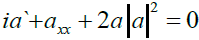
Establishing, for the observation by the LMI, the scenario of conformational change in the filamentary helicoids as shown in Figure 7b one can assume that a localized oscillatory field in the shear layer interacts with the filament helicoids, in an analogous manner as the vibrational field in the above model. The transition from one helicoidal conformation into the other can be described by the nonlinear Schrödinger equation (NLS) for the complex amplitude a=a(x,t) expressed in the non-dimensional form, by
 (7)
(7)
Where a prime and the subscript x designate the partial derivatives with respect to time t and arc wise parameter x, respectively [44]. Solitons, as localized in non-dispersive system, are stable and can propagate, without energy loss or dispersion, to larger distances than wave-packets of linear waves. They provide an efficient means, in a single event of the local conformational transition, for extracting the energy and for transferring it to distant location, meaning that the energy is not dissipated but spent for the new helicoidal selforganization [43].
The «toy model» starts from the initial state and the local conformation represented by the potential in terms of a scalar variable. The potential energy is modeled by an asymmetric φ4 double well potential V(φ),
V(φ) = ε(φ+ δ)2 (φ2 – 2/3 φδ + 1/3φ2–2) (8)
Where δ is the asymmetry parameter, ranging from-1 to 1, and ε is a small parameter. The two minima are placed at φ = ± 1 [43]. The amplitude field a(x,t), interacts with the conformational field φ(x,t). The change in conformation is realizable when the interaction is specified by a potential U(a,φ) = ˄|a|2φ2, with ˄ being a positive parameter. The combined potentials (V+U) are made to increase with |a| at the energy minima so as to lower the barrier for a folding transition [43]. The corresponding free energy density functional is
 (9)
(9)
Where the asterisk stands for the complex conjugate. The equations derived from the variation principle with [9] as the Lagrangian density make feasible numerical simulations for the conformational transformation of helicoids [43]. Tentative interpretation of the conformational transition process may be based on the «toy model» of Caspi and Ben-Jacob (Figure 7c(i)-c(iv)). (i). The initial helicoidal conformation characterized by constant curvature, is locally metastable along the filament; (ii). The NLS non-topological soliton is generated and moves in the upward direction along the helicoids; (iii). The soliton interacts with the curvature field and causes transition to the minimal energy configuration; (iv) The minimum energy (ground) state is featured by another value of curvature different from the initial one [43]. Thus, the micrograph in Figure 7a and 7b can be interpreted as the transition of a helicoids from one conformation (in the high energy state) into another one (in the low energy state).
High density array
Formation of network pattern of bistable coiled helicoids: In the high density array of vortex filaments (Figure 1a right) the interaction of secondary coherent structures with localized strain fields for N ≳ 20, leads to the formation of bistable coiled thick filament-, ribbon-, and tubular-ribbon- (-helicoids) called “complexes” and their organization into complex network pattern (Figure 8a). Refinement of the micrograph reveals characteristic patterns (Figure 8b), while the reconstruction in Figure 8c, reveals that filamentary and ribbon helicoids are aligned on a 1D lattice (red lines). By increasing N, the “complexes” tend to fill up the space of the lattice cells, taking orientation of the coiling axes either at ∼ 450 to the right, or at ∼ (-) 450, thus forming a high complexity pattern. Such organization of the “complexes” indicates the tendency to fill up the empty space inside the cells of 2D lattice and to reduce the energy of the network system. By further increase of N, these structures, especially those of larger coiling radius, tend to move vertically out of plane and form a 3D organization of double layers, whereby the packing density in the plane is reduced. This indicates a tendency to promote an efficient energy dissipation rate and to reach the energy minimum via formation of hierarchically more complex organization. Such a configuration may be possible only by forming «complexes» out of a plane, which causes their stretching within the limit of being elastic. Thus 3D layered organization of «complexes» vertically stacked one above another indicates the architecture of a super-complex network.

Figure 8) Complex pattern of straight and angular bistable coiled filament bundles, thick filaments and ribbons, formed on the array of secondary structures. (a) Optical micrograph showing complex organization of ribbon helicoids and thick filaments bistable coiled into conical helicoids with progressively decreasing coiling radius. (b) A refined micrograph of the pattern in Fig.8a reveals that bistable coiled helicoids as well as ribbon helicoids, called «complexes», with the coiling axes oriented in various directions, are interconnected into a supercomplex network. (c) Schematic reconstruction of the supercomplex network reveals that thick filaments and ribbons, as well as their «complexes» may be put on 1D lattice indicating the architecture.
In the following sections we shall consider the formation of “complexes” for N ≥ 20 and their organization into super-complex network, as well as the network breakdown when the number of pulses reach the critical value, Ncr.
Formation of thick-filament bistable coiled conical helicoids: The thickfilament «complex» in the network Figure 8 is a conical left-handed helicoid coiled around an axis tilted to the right (Figure 9a(i)). Such coiling is generated by twisting the filament at the one end, while the other end is pinned at the point defect (Figure 9a(ii)). The «complex» in (Figure 9a(iii)) shows a conical right-handed helicoids coiling around an axis tilted to the left with the radius progressively decreasing from R=Rmax to R ∼ 0. Such a conical helicoids is formed by the action of a double valley twisting potential on the filament pinned at (quasi-)static strain field (Figure 9a(iv)). Although (quasi-) static strain fields may be an assembly of virtual point defects, they cause pinning of filaments similar to the real defects [11]. In more general sense, the interaction of topological point defects (whether they are real or virtual), with the filament is analogous to the action of the «source» or «sink» which generates similar conical trajectory of a charged particle in the magnetic monopole, being equivalent to vortex filament embedded in a source or sink flow. This effect was experimentally demonstrated by Petitjeans [45] by injection of the small dye jets into a fluid (Figure 9b(i)) visualizes angular bistable helicoids; the upper coiled segment is conical due to the filament pinning at the point defect. The lower segment with the left handed coiling has mostly constant radius. These segments, connected under an angle of α 1200 (Figure 9b(ii)), are generated by strongly asymmetric, twisting double valley potential. The reconstruction in Figure 9b(iii) reveals that pinning center besides the conical coiling causes also splitting of a thick filament into two filaments of the smaller core size (Figure 9b(iv)).

Figure 9) Configurations formed by thick filament coiling and bistable coiling with progressively decreasing coiling radius. (a) (i) Rendering of the optical micrographs reveals details of the conical-helicoids. (ii) Formation of conical-helicoids of a thick filament pinned at one end at the (quasi-)static strain field, and exposed to the twisting strain field at the opposite end. (iii) Optical micrograph showing a conical bitable coiled helicoids. (iv) Formation of such structure occurs under action of a double-valley twisting potential on the pinned filament. (b) (i) Rendering of the optical micrographs reveals angularly bistable coiled helicoid which is pinned at the left side. (ii) Reconstruction reveals bistable coiling of the filament caused by twisting doublevalley potential, and formation of a conical helicoids. (iii) Schematic illustration of vortex filament splitting and conical coiling. (iv) Schematic illustration of the filament splitting into two thinner filaments, one straight, and another one turned by ∼ˇ900 to the right at the localized (quasi-)static strain field.
Formation of isometric vortex ribbon helicoids: The ribbon helicoid «complex» in Figure 10a(i) at both ends become thick-filaments, schematically shown in Figure 10a(ii) is formed when the local oscillatory strain field executes a strong twisting action on the ribbon [12]. It resembles the isometric spiral ribbon helicoids and may be compared to one in Figure 10a(iii). The continuum theory for the chiral ribbons by Helfrich and Prost [46] is built on the assumption that the ribbon is isometric, i.e., that it does not support the elastic strain. A chiral twist can be imparted to isometric or non-stretchable (inextensible) ribbons only by winding them over the surface of a cylinder [47,48]. The helical ribbons in Figure 10a(i) and 10a(ii) represent examples of more general problems of conformational instability [47-50]. The conformational instability depends on the characteristics of the ribbon helicoids such as the helical pitch, the torsional rigidity C and the elasticity, given an inextensible ribbon of the bending stiffness A and B [50].

Figure 10) Configurations formed by the ribbon coiling. (a)(i) Rendering of the optical micrographs reveals helicoidal coiling of non-isometric ribbon which is transformed into thick filaments at both sides. (ii) Schematic illustration of such a ribbon helicoids. (iii) Numerically simulated ribbon helicoids with the helical pitch, h, as variable parameter (expressed by the angle Φ. Notice, that the ribbon helicoids in Figure 10(a) (i) can be identified with the case of Φ =130. (Reprinted with permission Figure 3 from S. Zhao, S. Zhang, Z. Yao and I. Zhang, Phys. Rev. E 74 032801 (2006). Copyright (2006) by the American Physical Society). (b) (i– iii) Rendering of the optical micrographs reveals tubular-ribbon helicoids, specifically the screw helicoids. (iv) Numerical simulation of tubular-ribbon low density coiling. (Courtesy of Prof. H. Havlicek, of TU Vienna, from H. Havlicek, “Advanced Descriptive Geometry”, http://www.geometrie.tuwien.ac.at/havlicek/ergaenz.html (v) The increase in N causes increase in the coiling density and formation of the screw helicoids characterized by the coil thickness d, and the pitch, h (h > d). Comparison of this structure with (i), (ii) and (iii), indicates that dense coiled tubular-ribbon helicoids is the screw helicoids.
The rotation of the crossection of a not stretchable but deformable curve that represents the ribbon of the arc length s (0 ≤ s ≤ L, where L is the total length of the ribbon), about the centerline is expressed by the twist angle α(s). The free energy Ƒ of the ribbon take the form
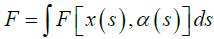 (10)
(10)
Where F is the free energy density functional and depends on the position vector x(s) and the twist angle (s) [51].
Similarly, the configuration of the centerline curve of ribbon can be described by an orthonormal triad of unit vectors {e1,e2,e3}, where e1 and e2 are oriented along the principal axes in the cross-sectional plane of the ribbon and e3=dx/ ds is the unit tangent to the centerline curve at the point x specified by s. The vectors ei (i=1,2,3) satisfy the generalized Frenet equations,
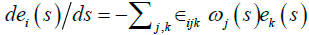 (11)
(11)
where εijk is the completely antisymmetric tensor of third order and ωj(s) (j=1,2,3) are the generalized torsion parameters. The generalized torsions ωj(s) are given, in terms of the curvature K, torsion τ, and the angle α, by
ω1 = K cos α, ω2 = K sin α and ω3 = τ + dα/ds, (12)
The free energy Ƒ then has the form
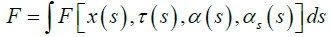 (13)
(13)
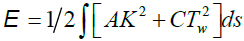
where αs(s) = dα(s)/ds is the twisting angle, per unit length, of the cross section along the centerline of the ribbon. The functional F depends on both the elasticity of material, specified by elastic constants, and geometrical shape of the cross-section. The corresponding free energy density of the elastic ribbon is:
F = F(K,τ, α,αs) = (A/2) K2cos α+ (B/2) K2sin α + C(τ+αs – τ0)2 (14)
where τ0 is the spontaneous torsion [50]. We employ as the unit of temperature kBT=1, and consequently A, B, and C have dimension of length. For an isotropic material, as in the case with an a vortex ribbon, the rigidities can be expressed in terms of the shear modules μ, Young’s modulus E, and the principal moments of inertia, which depend on the shape of the cross section.
For a ribbon helicoids, the rigidity parameters A and C are fixed and one can find the pitch angle Φ between two neighboring helical coils for anisotropic and isotropic ribbons. Concentrating on the isotropic ribbons, one finds for the ratio C A ≈ 4μ E = 2 (1+σ `) the pitch angle to be
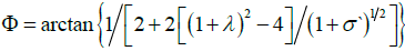 (15)
(15)
where σ ` (-1≤ σ `≤ ½) is the Poisson’s ratio and λ= τ0/τ. The right side of Eq (15) is real only when λ > (5/2)1/2-1, which implies that the isotropic helical ribbons with λ < (5/2)1/2-1 are unstable. Typical configurations of helical ribbons with the pitch angle 100< Φ ≤ 500, obtained numerically by Zhao et al., [50], is illustrated in Figure 10a(iii). Comparison of these simulated ribbon helicoids with the helicoids in the micrograph (Figure 10a(i)), gives the pitch angle Φ ∼ 130 for the closest agreement. one finds form of equation (15) with the parameter Taking λ ∼ 0.6 in the stability range of Φ ∼ 130, one finds form Eq (15), with the parameter σ`∼ -0.84 >-1. Based on this σ value, the ratio of torsional and bending rigidity constants of the ribbon is, C/A ∼ 0.32. The measurement of the ribbon in Figure 10a(i) shows that its length and width are L ∼ 700 μm, and W ∼ 40 μm, respectively, and thus that the aspect ratio, A = L/W ∼ 17.
Formation of non-isometric vortex tubular-ribbon helicoids: The tubular-ribbons helicoid “complexes” in Figure 10b(i)-b(iii), show significant bending of the coiling axis, being indicative of certain degree of elasticity. In contrast to the above case, this type of helicoids is able to be created if the ribbon is stretchable, but any lateral bending along the ribbon axis is forbidden [46,47]. The structure is non-isometric spiral tubular-ribbon helicoids with geometry restricted to the family of ruled surface helicoids. The tubularribbon helicoids with the low density coiling, and with the high density one are shown in Figure 10b(iv) and 10b(v) respectively. The last one is the screw helicoid, similar to those in Figure10a(i)-a(iii). Denoting the radius of the screw helicoids by R, the coil thickness by d, and the helical pitch by h, as shown in Figure 10b(v), the helicoids can be characterized by the ratio ℒ=h/d. Measurement on the Figure 10b(i)-b(iii) gives 2R∼50 μm, d ∼18 μm and h ~28 μm, with ℒ=1.6. For N ≥ 25, the helicoidal pitch h decreases while d increases tending to h∼d, or ℒ=1. The ribbon shape in the Figure 10b(i)-b(iii) can only be generated if the plane of the circle makes helical) horizontal motion (orthogonal to the vertical axis of the screw) [51]. The shape instability of a ribbon transforming it into ribbon-helicoid and into tubular–ribbon helicoid is described by a model which treats the helicoid as a real surface of finite thickness, elasticity, and stifness.
Reconstruction of the localized strain fields which generate complex network pattern of Figure 8, leads us to a simplified representation of Figure 11. The bistable coiling fields are represented by 2D maps of a double walley twisting potential (red and blue areas), while the pinning centers are marked with rose spots. Although randomly distributed, these local strain fields can be put on the nodal points of 2D lattice, being indicative of a certain degree of regularity in their spatial distribution (Figure 11). Their interaction with filaments and ribbons gives rise to a network-pattern of interconnected «complexes». With increasing N, complexes show tendency to move in the vertical direction out of the plane, and form a layered network which resembles the architecture of biopolymers and of the biological systems as exemplified by the Colicin E1, a member of proteins comprising angular bistable ribbon helicoids organized in a layered structure [31].

Figure 11) Analysis of the pattern in Figure 8(a-c) shows that random distribution of localized strain fields actually lies on nodes of an almost regular 2D lattice.
Breakdown of network pattern of bistable coiled helicoids: When the number of pulses reaches the critical value, Ncr, at which the stretching of filaments and ribbons surpasses the elastic limit, the possibility for the «complexes» to move out of a plane and establish 3D organization is exhausted, the system faces crisis. The crisis occurs at Ncr ≥ 30, causing breakup of the super-complex network and of the «complexes» as well. Rather than reaching the higher organizational state, the system catastrophically passes into a downgraded chaotic pattern (Figure 12a). The image refinement and magnification reveals breakdown of vortex-filament helicoid and bistable helicoid «complexes» in the form of the «pigtails» (Figure 12b(i)), twisted and writhed filaments (Figure 12b(ii)), looking like those numerically simulated by Goldstein et al., [52] (Figure 12b(iii)). It also reveals that broken ribbon helicoid «complexes» generate small segments of the Scherk surface geometry [11]. The ribbon width W, somewhat increases while its thickness decreases in agreement with the diagram in Figure 8 of (12).

Figure 12) Micrographs of breakdown structures of the filament helicoids, bistable coiled, ribbon, and tubular ribbon helicoids.(a) The pattern of broken filament and ribbon helicoids. (b)(i) Broken segments of the filament helicoids and (ii) bistable coiled helicoids in the form of «pigtail» structures. (iii) Numerically simulated structures (48). (Courtesy of R.E. Goldstein: Reprinted with permission Figure 2 from R.E. Goldstein, T.R. Powers, and C. H. Wiggins, Phys. Rev. Lett, 80 5232 (1998). Copyright (1998) by the American Physical Society). (c) (i) Typical segments of the screw helicoids. (ii) Rippled tube bent and merged with the background fluid.
Breakdown of tubular-ribbon helicoid «complexes» at Ncr ≥ 30, occurs in a different way. With increasing N, the coil density increases up to the critical point beyond which coils reach a state of overcritical density and merge into a «rippled tube» (Figure 12c(i)). However, the diameter of the tubular-ribbon helicoid does not change, so that the rippled-tube has the same diameter. The change in the coil thickness, d, and of the helical pitch h for the tubular-ribbon helicoid as function of N, is shown in the diagram in Figure 13. For N>15, both parameters d, and h, are constant, while for 20 ≤ N ∼25, the helical pitch decreases and d increases, leading to formation of the screw helicoid. The subsequent pulses increase the coiling density and enhance interaction between the neighboring turns of the coils. Further increase of N causes progressive decrease in h, so that neighboring turns approach to each other while accompanied by a simultaneous increase in d, until h ∼ d for N ≥ 27. Beyond N ∼ 30, the helical pitch becomes h<d, and eventually h → 0, causing coalescence of the neighboring turns with a catastrophic transformation of a tubular-ribbon helicoid into a rippled tube, being a lower complexity structure. The Figure 12c(i) shows the screw helicoid under the transition into the rippled tube of h ∼ 22.5 μm and d ∼25 μm, being characterizeded by ℒ=h/d ∼ 1. The other example of Figure 12c(ii) shows a rippled tube partially merged with the background fluid. The process is not homogeneous because the ripples seen in the central part have h ∼ 19 μm, and d ∼ 22 μm, with ℒ=0.8, while, at both ends of the tube (where merging with the background fluid is stronger), the ripples have h ∼ 20 μm and d ≥ 35 μm, with ℒ ≲ 0.57 ~ 0.5.

Figure 13) Variation of the parameters d (coil thickness) and h (helical pitch) of a tubular-ribbon helicoids as function of the number N of pulses. The diagram shows nonlinear behavior of both parameters with N. The parameter d gradually increases for N ≥ 20, and, for N ~ 27, saturates to d ~ 22 μm. The parameter h monotonically decreases reaching h ~ 22 μm for 25 < N < 27. At about N=27, the both parameters take the same value, i.e., d ~ h ~ 22 μm. The helical screw (screw helicoids), is formed in the interval 20 ≲ N ≲ 30. However, for N > 30, the parameter h suddenly decreases so that the neighbor turns of the coil come close and merge together, whereby and tubular-ribbon helicoids (screw helicoids) is transformed into rippled tube. (legend: TR- tubular-ribbon; TRH – tubular-ribbon helicoids; RT – Rippled tube).
The fact that the ripple density is larger at the both ends of the tube than in the center, indicates the formation of a standing wave, with compression of ripples at the both ends and rarefaction in the center. Rough estimation from the micrograph in Figure 12c(ii) gives the wavelength of the standing ripples of ∼ 110 μm. It also suggests that the breakdown of the screw helicoids with increasing N may be characterized by some phenomenological parameter ℒ. Measurement on the micrographs indicates that the screw helicoids exist for ℒ ∼ 1.6, rippled ones for 1.2 ≳ ℒ ≳1, and for 1 > ℒ ∼ 0.5, a rippled tube merges with the background fluid. Interpretation may be based on the fact that increase of the coil density promotes interaction between neighbor turns of the coil with simultaneous increase of diffusion and decrease of the fluid circulation in the vortex ribbon, Γ ribbon. The decrease of the Γ ribbon continues with increasing N, until it becomes comparable with or smaller than the diffusion coefficient D between the coils (Γ ribbon ≲ D). Eventually, at N=Ncr, the high coil density becomes overcritical, so that strong diffusion of the coil causes transformation of the screw helicoids into rippled tube. With further increase of N, a rippled tube interacts with with the background fluid thus continuing to decrease the fluid circulation, Γ ribbon, leading to merging of rippled tube with the background fluid.
This study is focused on multi-pulse laser-matter interaction which causes the formation of coiled, bistable-coiled filaments and ribbons or “complexes”, as well as their organization into patterns. The hypothesis, that formation of complex bistable coiled structures depends on the number of pulses and that the complexity of their organization depends on the initial vortex filament density, has being confirmed in this study. Their organization ranges from a simple random pattern to the layered interconnected super-complex network formed in a multi-stage organizational process.
The individual (separated) filaments, ribbon coils and helicoids in a random pattern show conformal transformation or transition from one type of helicoids of higher energy state into another type of lower energy state which is mediated by the NLS non-topological Davidov’s-like soliton. This indicates a great similarity with conformal transformation of some biological molecules (proteins). From the biochemical and physical characteristics of several molecular springs and ratchets they may be assumed as analogous to eukaryotic molecular engines.
The pattern formation in a high density filament array is a multistage process starting with vortex filaments as basic structures. In the next stage, they become organized into bundles, thick filaments, ribbons, and tubularribbons. The increase in N, causes transformation of filaments into coiled and bistable coiled helicoids and of ribbon into ribbon helicoids as well as their organization into network on 2D lattice. Further increase of N causes tendency of the network organization to become 3D layered structure. The transformations follow the scenario in which topological complexity of the new structure increases with the number of pulses, thus realizing configurations with more efficient energy relaxation.
The number of pulses, as the critical parameter for the filament and ribbon transformations as well as their organization is equivalent to some critical oscillatory frequency. Such transformations under some oscillatory field appear as a rather general phenomenon in condensed matter physics, molecular physics, biology and other systems at all spatial scales, from the atomic-one for superfluid He, to nano-and micro-scale for the polymers and biopolymers, up to the astrophysical scale.
Acknowledgement
Y.F. was partially supported by a Grant-in-Aid for Scientific Research from the Japan Society of Promotion of Science (Grant No. 16K05476). S.L. was also partially supported by the Croatian Science Foundation (No. IP-2014-09-7046). S.L. is grateful to Prof. Norman J. ZabuskyϮ, Department of Complex Systems, Weizman Institute of Science, Rehovot, Israel, for illuminating discussion and for the suggestion of the term «supercomplex organization» as the best description of the observed structures.
(ϮProf. Zabusky passed away at the beginning of February, 2018).
REFERENCES
- Ricca RL, Moffatt HK. Topological Aspects of the Dynamics of Fluids and Plasmas, Dodrecht: ed by H.K. Moffatt, Kluwer. 1992;225-236.
- Ricca RL, Berger MA. Topological ideas and fluid mechanics. Phys Today. 1996;49:28-34.
- Priest E. Sunspots reveal their dark side. Phys World. 2003;16:19-21.
- Berloff NG, Svitsunov BV. Scenario of strongly nonequilibrated Bose-Einstein condensation. Phys Rev A. 2002;66:013603(1-4).
- Eltsov VB, Blaauwgeers R, Kopnin NB, et al. Transitions from Vortex Lines to Sheets: Interplay of Topology and Dynamics in an Anisotropic Superfluid. Phys Rev Lett. 2002;88:065301(1-4).
- Schwarz KW. Three-dimensional vortex dynamics in superfluid 4He: Line-line and line-boundary interactions. Phys Rev B. 1985;31:5782.
- Liu C, Lee J, Gary DE, et al. The Ribbon-like Hard X-Ray Emission in a Sigmoidal Solar Active Region. Astrophys J. 2007;658:127-130.
- Fukumoto Y, Lugomer S. Instability of vortex filaments in laser-matter interactions. Phys Lett A. 2003;308:375-380.
- Lugomer S, Fukumoto Y. Hierarchical instability of a vortex ring array in multipulse laser-matter interactions. Fluid Dynamics Res. 2005;36:277-291.
- Lugomer S. Micro-fluid dynamics via laser-matter interactions: Vortex filament structures, helical instability, reconnection, merging, and undu-lation. Phys Lett A. 2007;361:87-97.
- Lugomer S, Fukumoto Y. Generation of ribbons, helicoids, and complex Scherk surfaces in laser-matter interactions. Phys Rev E. 2010;81:036311(1-11).
- Fraser WB, Van der Heijden GHM. On the theory of localized snarling instabilities in false-twist yarn processes. J Eng Math. 2008;61:81-95.
- Thomson JM, Van der Heijden GHM. Supercoiling of DNA plasmids: mechanics of generalized ply. Proceedings R Soc London A. 2002;458:959-985.
- Calini AM, Ivey TA. Knot types, Floquet spectra, and finite-gap solutions of the vortex filament equation. Math and Computers in Simulation. 2001;55:341-350.
- Zhou G, Zhang Z, Yu D. Growth morphology and micro-structural aspects of Si nanowires synthesized by laser ablation. J Cryst Growth. 1999;97:129-135.
- Wang ZL, Nanostructures of zinc oxide. Materials Today. 2004;7:26-33.
- Wang ZL, Kong XY, Ding Y. Piezoelectric nanorings and nanosprings. Microsc Microanal. 2004;10:(Suppl 2)528-529.
- Korgel BA, Materials science. Self-assembled nanocoils. Science. 2004;303:1308-1309.
- Tanda S, Tsuneta T, Okajima Y, et al. Crystal topology: A Möbius strip of single crystals. Nature. 2002;417:397-398.
- Chen X, Motojima S. Vapor phase preparation and some properties of carbon microcoils. KONA. 2006;24:222-227.
- Szabo A, Fonseca A, Magy JB, et al. Structural origin of coiling in coiled carbon nanotubes. Carbon. 2005;43:1628-1633.
- Motojima S, Chen X. Preparation and characterization of carbon microcoils. Bull Chem Soc Japan. 2007;80:449-455.
- Gao R, Wang ZL, Fan S. Kinetically controlled growth of helical and zigzag shapes of carbon nanotubes. J Phys Chem. 2000;104:1227-1234.
- Yu M-F, Dyer MY, Chen J, et al. Locked twist in multiwalled carbon-nanotube ribbons. Phys Rev B. 2001;64:241403(1-4).
- Tonomura A, Kasai H, Kamimura O, et al. Observation of individual vortices trapped along columnar defects in high-temperature superconductors. Nature (London). 2001;412:620-622.
- Bellesia G, Fedorov MV, Timoshenko EG. Structural transitions in model β-sheet tapes. J Chem Phys. 2008;128:195105(1-7).
- Frette V, Tsafrir I, Guedeau-Boudeville MA, et al. Coiling of cylindrical membrane stacks with anchored polymers. Phys Rev Lett. 1999;83:2465-2468.
- Jian X, Wang D, Liu H, et al. Controllable synthesis of carbon coils and growth mechanism for twinning double-helix catalyzed by Ni nano-particle. Composites Part B. 2014;61:350-357.
- Grason GM, Bruisma RF. Chirality and Equilibrium Biopolymer Bundles. 2007.
- Panyyukov S, Rabin Y. On the deformation of fluctuating chiral ribbons. Europhys Letters. 2002;57:512-519.
- White D, Musse AA, Wang J, et al. Toward elucidating the membrane topology of helix two of the colicin E1 channel domain. J Biol Chem. 2006;281:32375-32384.
- https://booksite.elsevier.com/samplechapters/9780123694706/Sample_Chapters/02-Chapter¬_1.pdf
- Krause D, Teplin CW, Rogers CT. Optical surface second harmonic measurements of isotropic thin-film metals: Gold, Silver, Copper, Aluminium and Tantalum. J Appl Physics. 2004;7:3626-3634.
- Li C. Nonlinear Optics. Polarization Theory of Nonlinear Medium. Shangai and Springer Nature Singapore Ptv Ltd., 2017. Ed by Shangai Jiao Tong Univ. Press.
- Johnson PB, Christy RW. Optical constants of transition metals: Ti, V, Cr, Mn, Fe, Co, Ni and Pd. Phys Rev B. 1974;9:5056-5070.
- Abu Arqub O, El-Ajou A, Momani S. Constructing and predicting solitary pattern solutions for nonlinear time-fractional dispersive partial differential equations. J Computational Physics. 2015;293:385-399.
- Abu Arqub O. Fitted reproducing kernel Hilbert space method for the solutions of some certain classes of time-fractional partial differential equations subject to initial and Neumann boundary conditions. Computers & Mathematics with Applications. 2017;73:1243-1261.
- El-Ajou A, Abu Arqub O, Momani S, et al. A novel expansion iterative method for solving linear partial differential equations of fractional order. Applied Mathematics and Computation. 2015;257:119-133.
- El-Ajou A, Abu Arqub O, Momani S. Approximate analytical solution of the nonlinear fractional KdV-Burgers equation: A new iterative algorithm. J Computational Physics. 2015;293:81-95.
- Goldstein RE, Goriely A, Huber G, et al. Bistable helices. Phys Rev Lett. 2000;84:1631-1634.
- Goriely A, Tabor M. Spontaneous helix hand reversal and tendril perversion in climbing plants. Phys Rev Lett, 1998:80;1564-567.
- Gorieli A, Tabor M. Nonlinear dynamics of filaments. Nonlinear dynamics. 2000;21:101-133.
- Caspi S, Ben-Jacob E. Conformation changes and folding of proteins mediated by Davidov's soliton. Phys Lett A. 2000; 272:124-129.
- Caspi S, Ben-Jacob E. Toy model studies of soliton-mediated protein folding and conformation changes. Europhys Lett. 1999;47:522-527.
- Petitjeans P. Stretching of a vortical structure: filaments of vorticity. Europhys News. 2003;34:20-23.
- Helfrich W, Prost J. Intrinsic bending force in anisotropic membranes made of chiral molecules. Phys Rev A. 1988;38: 3065-3068.
- Ghafouri R, Bruisma R. Helicoid to spiral ribbon transition. Phys Rev Lett. 2005;94:138101(1-4).
- Selinger RLB, Selinger. VJ, Malanoski AP, et al. Shape selection in chiral self-assembly. Phys Rev Lett. 2004;93: 158103(1-4).
- Panyukov S, Rabin Y. On the deformation of fluctuating chiral ribbons. Europhys Lett. 2002;57:512-519.
- Zhao S, Zhang S, Yao Z, et al. Equilibrium conformation of polymer chains with noncircular cross section. Phys Rev E. 2006;74:032801(1-4).
- http://www.geometrie.tuwien.ac.at/havlicek/ergaenz.html
- Goldstein RE, Powers TR, Wiggins CH. Viscous nonlinear dynamics of twist and writhe. Phys Rev Lett. 1998;80:5232-5235.