


Extraction of a vacuum energy conforming to Emmy Noether's theorem
Received: 25-Jul-2023, Manuscript No. puljmap-23-6611 ; Editor assigned: 27-Jul-2023, Pre QC No. puljmap-23-6611 (PQ); Accepted Date: Aug 08, 2023; Reviewed: 29-Jul-2023 QC No. puljmap-23-6611 (Q); Revised: 01-Aug-2023, Manuscript No. puljmap-23-6611 (R); Published: 10-Aug-2023
Citation: Sangouard P. Extraction of a vacuum energy conforming to Emmy No Ether��?���¢??s theorem. J Mod Appl Phys. 2023; 6(3):1-19.
This open-access article is distributed under the terms of the Creative Commons Attribution Non-Commercial License (CC BY-NC) (http://creativecommons.org/licenses/by-nc/4.0/), which permits reuse, distribution and reproduction of the article, provided that the original work is properly cited and the reuse is restricted to noncommercial purposes. For commercial reuse, contact reprints@pulsus.com
Abstract
This theoretical work corresponds to the hope of extracting, without contradicting the laws of thermodynamics or Emmy Noether's theorem, an energy present throughout the universe: that of the spatial quantum vacuum!
This article shows that - theoretically - it should be possible to maintain continuous periodic vibration of a piezoelectric structure. These vibrations generate current peaks for a fraction of the period. They are obtained by controlling automatically and at appropriate instants the action of an attractive Casimir force by a repulsive and ephemeral Coulomb force applied to return electrodes.
The attractive Casimir force appears between the two electrodes of a reflector and deforms a piezoelectric bridge embedded in its two extremities. The internal electric field created by the deformation of the piezoelectric bridge, attracts -from the mass- opposing moving charges. The systematic homogenization of the electric charges of one of the faces of the piezoelectric bridge with a Coulomb return electrode, creates a current peak and a Coulomb force opposite, ephemeral and greater than the Casimir force.
This Coulomb force cancels at least the action of the Casimir force and contributes to the disappearance of the deformation of the piezoelectric bridge. The device then returns to its initial position without electrical charges by using the deformation energy created by the Casimir force and stored in the piezoelectric bridge. The Coulomb force then disappears and the Casimir force deforms the bridge again.
During the homogenization of the electrical charges, a current peak I passing through an inductance induces a voltage peak U. These power peaks I. U are transformed – thanks to electronics without electrical power supply - into a continuous and usable voltage.
Casimir and Coulomb forces, vibrations, current or voltage peaks appear spontaneously and without any external energy input. The system vibrates because Casimir energy due to quantum vacuum fluctuations is constantly present.
To manufacture these different structures, an original micro technology is proposed. It should make it possible to produce the electronics and to control the very weak interfaces between the Casimir electrodes or the Coulomb return electrodes!
Keywords
Casimir; Coulomb; Vacuum Quantum energy extraction, Piezoelectric; MEMS
Introduction
The vacuums energy is the zero-point energy of all fields (tensorial Tand scalar) in space. In quantum field theory, this vacuum energy energy defined as reference, is the ground state of fields. It has been observed and shown theoretically that this so-called zero-point energy, is non-zero for a simple quantum harmonic oscillator, since its minimum energy is equal to E = h v /2 with v the natural frequency of the oscillator, and h the Planck's constant.
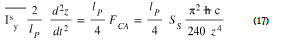
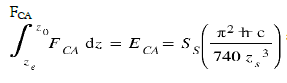
Originally, the Casimir effect is derived from statistical fluctuations of total vacuum energy and is the attraction (in general) between two plates separated by a vacuum [1-4]. In this approach, this Casimir energy is the part
of the vacuum energy which is a function of the zS separation of the Casimir plates.
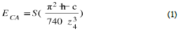
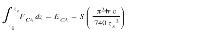
Thus, the Casimir force associated, is
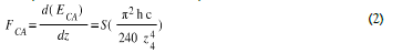
With ħ the reduced Planck constant, c the speed of light and S the reflector's surface, zs the distance between the plates. The presence of the reflecting plates excludes the wavelengths of the virtual particles higher than z0. They induce a pressure difference between the internal and external space of the 2 plates which pushes the plates against each other. (Figure. 1)

Figure 1: Casimir effect
Description of the principle used to "Extract" energy from the vacuum
The term vacuum energy is sometimes used by some scientists who claim that it is possible to extract energy from the vacuum, i.e., mechanical work, heat. These different hypotheses arouse great skepticism because they question a principle mathematically demonstrated by the theorem implying the conservation of energy by the mathematician Emmy Noether in 1915.
This theorem is accepted in physics and has never been challenged until now!
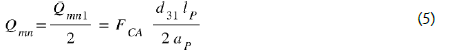
In fact, the problem is less to extract energy from the vacuum than to extract it without spending more energy that we cannot hope to recover! Thus, in a cyclic system on the model of a piston engine, moving from a position n°1 to n°2 and then from n°2 to n°1, the Casimir force being in 1 /zs4 , therefore greater in position (2) than in (1), necessarily seems to require more energy for a force of constant intensity to return to the position n° 1.
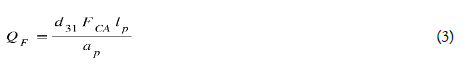
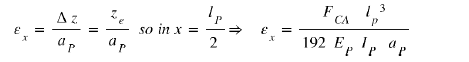
We know that in the case of a deformation perpendicular to the polarization of a piezoelectric layer, the fixed charges QF induced by the deformation of this piezoelectric layer are proportional to FCA and are therefore in 1/zs 4 .
Ref, does not depend on the common width bp = bs = bi of the structures [5, 6]. This point is important and facilitates the technological realization of these structures since it limits the difficulties to obtain a deep and straight engraving of the different structures. (Figure 2)

Figure 2: General representation of the structure.
d31 = piezoelectric coefficient (CN-1), lp, ap respectively length and thickness (m) of the piezoelectric bridge. These fixed electric charges on the two metallized faces of the piezoelectric bridge have opposite signs and attract mobile charges of opposite signs from the mass (Figure 3).
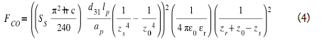

Figure 3: Nomenclature and Notations of the positions of electrodes for the device
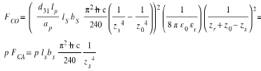
We note that Coulomb’s force FCO = 0 when the bridge has no deflection (zs = z0), so no electrical charges! This Coulomb Force in 1/zs10 can therefore become greater than that of Casimir which is in 1/zs4 .
As a preamble, we suppose that the events which induce the attractive force of Casimir are exerted in a universal, isotropic, perpetual, and immediate way. Let's consider a Casimir reflector device made of a parallelepipedic metallic and mobile electrode, of surface Ss1 = Ss2, separated by a distance z0 from a fixed metallized surface Ss3 (Figures 3-5).

Figure 4: Different view of the device

Figure 5: General configuration of the device: MOS grid connections (Face 2 of the piezoelectric bridge: red), Source connections (Face 1 of the piezoelectric bridge: green)
This parallelepipedic metallic Casimir reflector is rigidly linked, by a metallic finger, to a piezoelectric bridge embedded in its two ends. A displacement of the mobile Casimir electrode induces a deformation of the piezoelectric bridge and thus the appearance of ionic electric charges (Figures 4, 5).
We observe, in Figure 5, that the two surfaces Sp1 = Sp2 = bp * lp , of the piezoelectric bridge, are connected:
1. At the mobile electrode of the Casimir reflector through the metal finger (green), for the face n°1. Thus, the metallic surfaces Sp1 and the metallic parallelepiped Ss1 = Ss2 are equipotential.
2. At the grids of the switch’s circuits n°1 and n°2, for the face n°2 of area Sp2.
The Casimir force caused deformations of the piezoelectric bridge, which produce ionic electric charges generating an electric field. These fixed charges attract from the mass respectively mobiles electrics charges Qmp1 and Qmn2 on the metallics electrodes.
We observe in Figure 5:
1. The switch circuit n°1 made with enriched transistors MOSNE, MOSPE in parallel and with the threshold voltages VTNE, VTPE, (Figure 6),

Figure 6:) Circuit n°1
2. The switch circuit n°2 made with depletion transistors MOSND, MOSPD in series with threshold voltages VTND, VTPD (Figure 7)

Figure 7:Circuit n°2
3. The Circuit n°3, is an autonomous device operating without any electrical power source. It rectifies and accumulates the AC power delivered to the terminals of the inductance and transforms them into a usable DC voltage source.
The threshold voltages are technologically positioned as: 0 < VTPD < VTNE and VTPE < VTND < 0 The Figure 8 resumes this configuration

Figure 8: Distribution of the threshold voltages of enriched and depleted N and P MOS switches
We call VGRIDS the voltage, appearing simultaneously on the gates of all the MOS transistors, created by the electric charges moving on the face 2 of the piezoelectric bridge.
Their sign on the Sp1 and Sp2 surfaces depends on the polarization of the piezoelectric bridge obtained during its realization; the VGRIDS voltage on the MOS gates can be positive or negative.
The system (Casimir reflector, piezoelectric bridge, switches, return Coulomb electrode) finds the following cyclic situations (Figure 8).
1. When 0 <VGRIDS< VTND < VTNE, or VTPE< VTND <VGRIDS< 0 then switch 1 is OFF, and switch 2 is ON. The Coulomb returns electrode is grounded and isolated from piezoelectric bridge. There are no electric charges on the return electrode and no Coulomb’s force FCO appears.
2. When 0 < VTND < VGRIDS < VTNE, or VTPE< VGRIDS < VTND< 0, then switch 1 is OFF, and switch 2 is OFF. The Coulomb returns electrode is insulated from ground and the piezoelectric bridge. There are no electric charges on the return electrode
As long as the voltage on the gates of the enriched MOS of circuit 1 does not reach their threshold voltages, the state of circuit 1 and 2 do not change!
In these two situations, the only force that deforms the piezoelectric bridge is the Casimir force FCA
3. When 0 < VTND < VTNE ≤; VGRIDS, or < VGRIDS ≤;VTPE < VTND < 0, then switch 1 is ON, and switch 2 is OFF, Thus, the moving electric charges passing through switch 1 become homogenized between the return Coulomb electrode and the Sp1 face.
Let Sp1 = Sp2 = lp. bp = Sr be the surface area of the faces of the piezoelectric bridge and of the return electrode, facing the metallized face Sp2 of the piezoelectric bridge.
As there is no electric field in a conductor, the mobiles charges for example negative Qmn1, initially distributed on the metallic surfaces Sp1 are distributed on the surfaces Sp1 + Sr. The return Coulomb’s electrode has a charge
Between the faces Sp2 and Sr, with an opposite sign electric charge, appears an attractive force of Coulomb, parallel and opposite to the attractive force of Casimir [5]. (Figure 5 and 9)
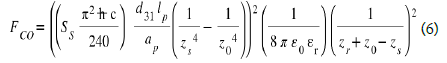

Figure 9: Polarization and applied force and load on a piezoelectric block
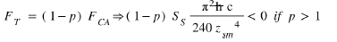
The threshold voltage of the MOSNE is adjusted so that the Coulomb force is triggered only when FCO = pFCA, with a chosen proportionality factor p. Then the total repulsion force Ft, variable in time, and applied to the piezoelectric bridge becomes

Repulsive, this force Ft induces a deformation of the piezoelectric bridge in the opposite direction, and the piezoelectric bridge returns or slightly exceeds (because of inertia) its neutral position, therefore towards its position without any electrical charge.
Calculation of the homogenization current
Since there is no electric field in a metal, the variation in time of the mobile charges on the initially grounded but now insulated coulomb return electrode follows, to a first approximation, the law of charge distribution on a short-circuited capacitor.
This time variation of the charges is given by the well-known exponential form of the charge of a capacitor according to the formula
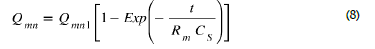
This variation stops when the electrical charges Qmn are uniformly distributed and equal to Qmn1/2 over the two electrodes Sp1 and Sr, so at time te = Rm Cs ln (2) (Eq. (5)). The time te is to reach this balance, with Rm the ohmic resistance of the metal track, Lin the coil inductance, Cs the capacitance formed by the electrodes.
An approximation of the duration of the homogenization of the electric charges and therefore of the duration of the current peak, gives  . It is based on an estimate to propagate in the resistivity part of the LIN inductance of about 10-5 Henri, plus the resistance of the MOS.
This current peak IIN circulating for the duration of time te is IIN
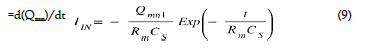
The time t =0 is counted from the closing of one of the transistors of circuit 1. This current peak is present even if the switch transistors close some time after, because the mobile charges have already propagated.
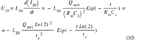
This current peak IIN crossing an inductance LIN during the time te induces a voltage peak UIN at the terminals of this inductance LIN as a function of time according to the usual formula:
An alternative AC voltage peak UIN with a maximum voltage at time t = 0, is therefore automatically recovered at the terminals of the solenoid LIN. This AC voltage peak can then be rectified to a direct DC voltage of a few volts, by suitable electronics operating without power supply.
An opposite, intense and ephemeral Coulomb’s force FCO = pFCA appears suddenly between return electrode and face 2. The piezoelectric bride is then, submitted to the force FCA (1-p) with p a factor of proportionality chosen by the value of the threshold voltages of the MOSE and MOSD.
The position ze of appearance of this Coulomb force corresponds to the following equation FCO = p FCA and is solve numerically, see equation 11 and Figure 10

Figure 10: Position ze of the mobile Casimir electrode when the Coulomb force occurs for zr = z0 =200A° ls = 500 μ bs = 150 μ lp = 50μm bp = 150μm ; ap = 10μm
4. As long as 0 < VTND < VGRIDS ≤ VTNE, or VTPE ≤VGRIDS < 0, the Coulomb force FCO continues to exist. The bridge deformation and the voltage on the MOS gates continue to decrease with the same expression of the different forces (Eq. 1, 3 ,4).
As long as the voltage on the gates of the MOSD of circuit 2 does not reach their threshold voltages VTND or VTPD, the piezoelectric bridge continues its movement to its initial position z0.
The return Coulomb electrode is again connected to ground. The Coulomb force FCO disappears. But the bridge, having acquired kinetic energy, spends it by inertia to continue its ascent towards z0 and even slightly exceeds its neutral position.
Still present, the Casimir force FCA is again the only one that applies! It attracts again the metallic surface SS2 against SS3 and the events described above are repeated.
The consequence is that the structure made up of the piezoelectric bridge, the connecting finger, the metal block forming the mobile Casimir electrode starts to vibrate.
With a frequency depending:
1. Of the Casimir restoring force, and of the Coulomb return electrode force therefore so with: a) the starting z0 and zr separation interface b) geometric dimensions of the different electrodes,
2. Properties of the piezoelectric bridge,
3. The choice of threshold voltages of the different MOS transistors
4. The choice of conductive metal
As we will see, this frequency is lower than the first resonance frequency of the moving structure if the initial interface z0 < 150 A° .
In conclusion, it seems that all the electro-physical phenomena leading to a vibration of the structure and thus to the production of a peak of electric power, are only the consequence of a single phenomenon. The one linked to the Casimir force - resulting from the fluctuations of the vacuum energy - but controlled by a Coulomb force.
Calculation of the behaviour of the structure
Let us calculate the evolution in time of the force of Casimir which is applied between the two electrodes separated by an initial distance z0. We use the theorem of angular momentum to this vibrating structure
With  S Axyz the angular momentum vector of the structure ISAxyz the inertia matrix of the structure with respect to the reference (A, x,y,z) and
  the rotation vector of the piezoelectric bridge with respect to the axis Ay, α the low angle of rotation along the y axis of the piezoelectric bridge (Figure 11)

Figure 11: Piezoelectric bridge Bending Moment, Deflection
We have
because z << lp
Because 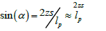
Let (Gp, x, y, z), (Gi, x, y, z), (Gs, x, y, z) be the barycentric points respectively of the piezoelectric bridge, the metal connecting finger and the metal block constituting the sole mobile of the Casimir reflector.
We have (Figure 4):
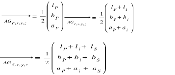
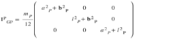
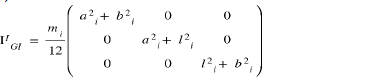
The inertia matrix of the bridge, in the frame of reference (Gp, x, y, z) is:
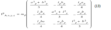
Taking Huygens' theorem into account, this inertia matrix becomes Eq. (13):
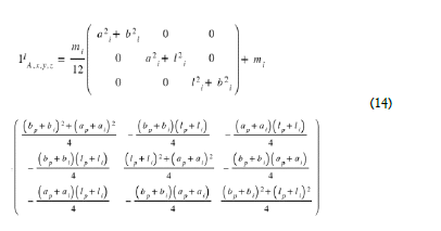
The inertia matrix of the finger is, in the frame of reference (Gi, x, y, z) is:
Taking Huygens' theorem into account, this inertia matrix become Eq. (14)
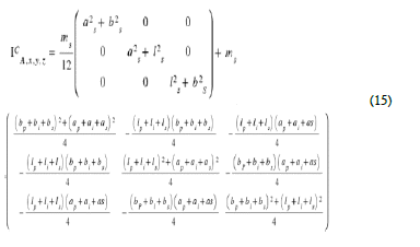
The inertia matrix of the reflector in the frame of reference (GS, x,y,z) is

Taking Huygens' theorem into account, this inertia matrix becomes: Eq. (15)
The total inertia of the structure becomes in the reference (A, x,y,z), IsA,x,y z = IPA,x, y, z + II A, x, y, z + Ic A, x, y, z with A at the edge of the recessed piezoelectric bridge .The angular momentum theorem applied to the whole structure gives
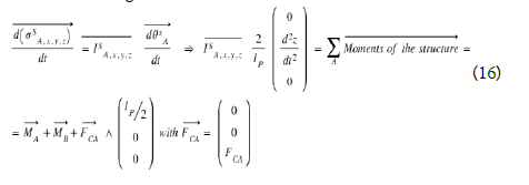
The structure rotates around the Ay axis. We know (see X), that the moments are MAY = MBY = - FCA lp /8.
Therefore:  Moments on the structure relative to the axe Ay = ¼.lp .FCA .
Any calculation done we obtain: (17) with  the inertia of the structure relatively to the axe Ay.
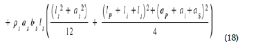
With  respectively the densities of the piezoelectric bridge, the intermediate finger and the mobile electrode of the Casimir reflector.
As long as 0 < VTND < VGRIDS < VTNE or VTPE < VGRIDS < VTND < 0 By equation 12, we obtain the differential equation which makes it possible to calculate the interval between the two electrodes of the Casimir reflector as a function of time during the "descent" phase when the Coulomb forces are not present
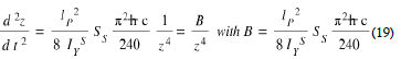
This differential equation (19) unfortunately does not have a literal solution and we programmed it on MATLAB to calculate the duration of this "descent" of free Casimir electrode. This duration depending on the desired value of the coefficient of proportionality p.
Just at the moment of closing circuit n°1, we have FCO = - p FCA with p a coefficient of proportionality ≥2 defined by the threshold voltages of the MOS interrupters. The total force FT exerted in the middle of the piezoelectric bridge just at the start of the charge transfer becomes: FT = FCA-FCO = FCA (1-p)
The "descent" time of the free Casimir electrode will therefore stop when FCO =-pFCA. This moment, we know that: VGRIDS =VTNE or VGRIDS = VTPE
1. The Casimir force is variable in time and its equation is (Eq. (2)):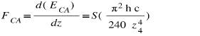
2. The mobile charges transiting from side 1 to the Coulomb electrode through circuit 1 variable in time are: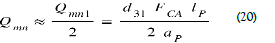
3. The Coulomb force, variable over time, acting in opposition to the Casimir force (Eq. (4)):
The "descent" of the free Casimir electrode stops when the inter electrode interface zs reach the position ze such that Eq 11:
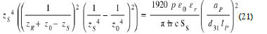
Figure 10 therefore gives the time td of the "descent" of the structure submitted to the Casimir force: This programmable equation depending on the coefficient of proportionality p, is calculable and will stop when the interelectrode interface zs has a value ze satisfying equation (21). At this instant the total force is
and the displacement of the mobile system reaches is maximum position zsm and changes direction, but as switch 2 is still open the Coulomb force persists.
During all the phase where 0 < VTND < VGRIDS ≤VTNE, or VTPE ≤VGRIDS < VTND < 0, the total force, variable over time and exerted at the center of the piezoelectric bridge, becomes:
The piezoelectric bridge subjected to this force then rises towards its neutral position. The Casimir inter electrode interval increases causing the Casimir force to decrease. As the deformations on the piezoelectric faces decrease, so do the electrical charge, resulting in a decrease in the Coulomb force? During the “ascent”, the FT force therefore rapidly approaches the starting FCA force. Let us calculate an approximation of the duration of this "rise». It is a maximization of this time because in fact the Coulomb force FCO stop when the circuit 2 close to ground another time.
As we don’t know the threshold voltage VTND or VTPD, we made this calculation as there are null.
In these MATLAB simulations we consider that the metal electrodes and the metal block are oxidized to a thickness allowing an interface between the Casimir electrodes of 200 A°. This modifies the mass and inertia of the vibrating structure.
It turns out that the choice of aluminum as the metal deposited on these electrodes is preferable given:
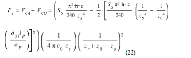
1. It’s easy oxidation in Al2O3 In these conditions, to know the time taken by the structure to "go back" to its neutral position, we must solve the following differential equation: (Eq. (22))
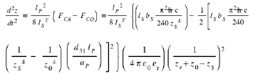
By posing 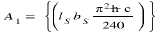 this differential equation concerning the "ascent" of the bridge is written
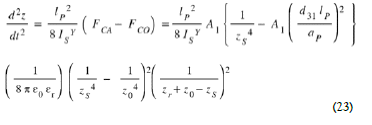
This differential equation (23) has no analytical solution and can only be solved numerically.
We programmed it on MATLAB. The properties and dimensions of the different materials used in this simulation are as follows (Table 1).
TABLE 1. Table of characteristics used for MATLAB and ANSYS simulations
| PZT | AlN | LiNbO3 | PMN-PT : | |
|---|---|---|---|---|
| Young Modulus (kg*m*s-2) / m²) | Ep=8.9*1010 | Ep=32*1010 | Ep=2.45*109 | Ep=150*10^9 |
| Volumic mass (kg m-3) | dp =7600 | dp=3255 | dp=4700 | dp=7920 |
| Piezoelectric coefficient d31 of the beam (C / (kg* m* s-2) | d31=200*10-12 | d31=2.400*10-12 | d31=6*10-12 | d31= 1450*10-12 |
| Length piezoelectric beam: lp (m) | 50 10- 6 | 50 10- 6 | 50 10- 6 | 50 10- 6 |
| Width piezoelectric beam: bp (m) | 150 10- 6 | 150 10- 6 | 150 10- 6 | 150 10- 6 |
| Thickness piezoelectric: ap (m) | 10 10- 6 | 10 10- 6 | 10 10- 6 | 10 10- 6 |
| Connecting finger length: li (m) | 10 10- 6 | 10 10- 6 | 10 10- 6 | 10 10- 6 |
| Width finger connection: bi (m) | 150 10- 6 | 150 10- 6 | 150 10- 6 | 150 10- 6 |
| Thickness finger connection: ai (m) | 10 10- 6 | 10 10- 6 | 10 10- 6 | 10 10- 6 |
| Mobile Casimir electrode block length: ls (m) | 500 10- 6 | 500 10- 6 | 500 10- 6 | 500 10- 6 |
| Mobile Casimir electrode block width: bs (m) | 150 10- 6 | 150 10- 6 | 150 10- 6 | 150 10- 6 |
| Casimir mobile electrode block thickness: as (m) | 10 10- 6 | 10 10- 6 | 10 10- 6 | 10 10- 6 |
2. Its low density increases and optimizes the vibration frequency of the structure by minimizing the inertia of the Casimir reflector and the parallelepipedic block that transfers the Casimir force.
The mass Mstructure of the vibrating structure is then:
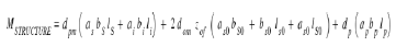
With dpm the density of the metal, as, bs, ls the geometries of the mobile metal part of the Casimir electrode sole, dom the density of the metal oxide, aso, bso, lso the geometries of the oxidized parts around the 6 faces of the metal block, dp the density of the piezoelectric parallelepiped:
Simulation of devices with different piezoelectric bridge
We present below the results of the MATLAB simulations carried out by numerically calculating of the differential equations (19) and (23). These numerical calculations give the vibration frequency of the structure which vibrates at a frequency lower than its first resonant frequency. This vibration frequency depends on the characteristics of the structure (Nature of material, geometric dimensions, coefficient of proportionality p = FCO / FCA…)). Annex X.
The metal used for the Casimir reflector block is Aluminum with a density of 2.7 g cm-3 and the Piezoelectric material = PMN-PT With these simulations, for an interval between Casimir electrode z0= 200 Angstroms, we obtain the evolution over time of the Casimir and Coulomb forces as well as the FCO/FCA ratio of Figures 12 to 27 below.
For a ratio of 1000, we have respectively: the maximum current delivered by the vibrating structure, the threshold voltage of the MOSE and the vibration frequency of the structure are respectively: 1.2 10-4 A, Vt = 3.2 V and 957000 Hertz
1. Evolution of the Casimir interface as a function of time during two periods: PMN-PT For the FCO / FCA ratio = 10000 induces a period of 3.85 10-6 s and a rise time of 21.3 10-9 s with a deflection of the bridge of 105 A °. The structure vibrates at 259.7 kHz. (Figure 12).

Figure 12:Plot of the evolution of the Casimir inter-electrode interval as a function of time over two periods and an Fco/Fca Ratio = 10000: Casimir inter-electrode interface = 200 A°
Due to inertia, at the rise sequence, the structure exceeds by 20 A° the initial 200 A° A ratio FCO /FCA = 1000 induces a period of 2.96 10-6 s and a rise time of 44.5 10-9 s with a deflection of the bridge of 50 A°. Due to inertia, the structure exceeds the initial 200 A° with 0.05 A°. The structure vibrates at 337.8 kHz: (Figure 13) For the ratio FCO /FCA = 2 (Figure 12) a vibration amplitude of just 0.27 A° and a period of 1.86 10-7 s is obtained (Figure 14)

Figure 13:Plot of the evolution of the Casimir inter-electrode interval as a function of time over two periods and an Fco/Fca Ratio = 1000: Casimir inter-electrode interface = 200 A

Figure 14:Plot of the evolution of the Casimir inter-electrode interval as a function of time over two periods and a Ratio Fco /Fca =2. Casimir interelectrode interface = 200 A
This low deformation of the PMN-PT piezoelectric bridge is mainly due to the extremely high piezoelectric coefficient d31 of 1450 (pC/N) of PMN-PT compared to 120 (pC/N) for PZT (Table 1). We observe the weak overshoot of the initial interface.
2. Evolution of the forces of Casimir and Coulomb: PMN-PT We obtain:
The evolution of the Casimir and Coulomb forces as a function: a) of the inter-electrode interface (Figure 15) and b)over time (Figure 16)

Figure 15: Materials = PMNPT: Coulomb and Casimir force as a function of the inter-electrode interface

Figure 16:Materials = PMNPT: Coulomb and Casimir force as a function of time. Start interface = 200A °
The FCO / FCA ratio as a function of time for an entire period (Figure 17).

Figure 17:Materials = PMNPT: Ratio p = FCO / FCA as a function of time, during a period of vibration. Start interface = 200A°, Maximum ratio chosen = 450
The break circuits n°1 triggering at time t =2.44 10-6 , suddenly induce a rise of the mobile electrode, therefore a sudden decrease in electric charges and grids voltages. We observe the gradual evolution towards the chosen ratio of 450 and then the sudden drop in this ratio as the electrodes regain their initial position (Figure 17).
3. Ratio FCO/FCA as a function of Casimir interval and current peak as a function of the ratio: PMN-PT
We observe (Figure 18) that for PMN-PT, a length of the piezoelectric bridge of 150 μm and a deformation of 10 A° of piezoelectric bridge, is sufficient to have a ratio = 1000.

Figure 18: Materials = PMN-PT: Coulomb Force / Casimir Force ratio as a function of the Casimir inter-electrode interface. Start interface = 200A°
On Figure 19, we see that a ratio of 2 gives a peak current of 7 10-7 A, while a ratio of 1000 produces a peak current of about 3.25 10-4 A, for the same time of homogenization of the charges of about 10-9 s

Figure 19: Materials = PMN-PT: Peak Current delivered by the structure as a function of the Fco / Fca Ratio. Start interface = 200A°
We see (Figure 20) that the Coulomb return force is less important for an initial interelectrode gap zr = 400A° than for zr = 200A° .

Figure 20:Materials = PMN-PT: Coulomb force for zr = 200 A° (Blue) and zr = 400 A° (Red) and Casimir force (Yellow, z0 =200 A°) as a function of the inter-electrode interface Starting interface = 200 A
4. peak current as a function of time and peak voltage across the inductance for 2 periods: PMN-PT
The following figures illustrate the peak current generated by the automatic vibrating structure with an inserted magnification showing the shape of this peak as a function of time (Figure 21) and its exponentially decrease during about 10-9 s. This current of about 1.2 10-4 A flowing through an inductor LIN of 3 10-5 Henri naturally generates a voltage of 4 Volts (Figure 22)

Figure 21: Materials = PMN-PT: Current peak as a function of time obtained over 2 cycles. Starting interface = 200A ° Ratio p=Fco /Fca=1000

Figure 22:Materials = PMN-PT: Voltage peak across the 4. 10-5 H solenoid as a function of the time obtained over 2 cycles. Starting interface = 200A °, Ratio p=Fco /Fca=1000
Note the exponential form of the current peak in each period. As the current peak cross an inductor, it induces by itself a voltage peak
5. peak voltage across the inductance and threshold voltage according to the desired.
It can be seen (Figure 23) that the automatic peak voltage obtained without any energy expenditure increases by a factor of 16 from 0.25 V to 4 V, when the ratio p = FCA / FCO changes from 2 to 1000. Similarly, the MOSE threshold voltage allowing these ratios increases from 0.2 V to 3.2 V (Figure 24).

Figure 23:Materials = PMN-PT: Voltage peak across the 4*10-5 H solenoid as a function of the FCO /FCA Ratio. Start interface = 200A °

Figure 24:Materials = PMN-PT: Threshold voltage of the Enriched or Depleted MOTS according to the FCO / FCA Ratio. Start interface = 200A°
6. Vibration frequency as a function of the FCO / FCA ratio and peak current as a function of the initial Casimir interval chosen: PMN-PT
Note (Figure 25), that for an initial interface z0 = 200 A°, and for a ratio FCO / FCA = 2, the vibration frequency of the structure is 3.50 MHz. It falls to 750 kHz for a ratio of 1000. These frequencies are still lower than the calculated first resonance of the structure, which is of the order of 7.94 Megahertz.

Figure 25:Materials = PMN-PT: Vibration frequency as a function of the FCO / FCA Ratio. Start interface = 200A°
This vibration frequency of the Casimir structure approaches that of the first resonance for weaker interfaces below 200 A°. But we are then confronted with the technological possibility of controlling such a weak interface. For a ratio FCO/FCA = 500, the maximum current delivered by the structure falls as a function of an increase in the initial Casimir interval (Figure 26).

Figure 26:Materials = PMN-PT: Current peak across the 2.10-4 H inductance as a function of the starting interval between Casimir electrodes
It seems that the piezoelectric material PMN-PT coupled with a conductor like aluminum is an interesting couple for our vacuum energy extraction structure.
Energy balance
In this chapter we make an assessment of the energies that pass through this system. In particular we show that the CASIMIR force is blocked in its evolution towards a collapse of its two electrodes, by a COULOMB force. It is much more intense but lasts an extremely short time because it is cancelled very quickly. Let us recall that the voltage thresholds of the MOS are by technological design as:
0 < VTND < VTNE, and VTPE< VTND < 0
1. Note that the mobile parallelepipedic metal electrode remains parallel to the fixed metal electrode when it moves! It simply transmits its movement to a piezoelectric bridge which deforms by bending.
2. The expulsion of entropy ΔS from the vibrating electrode of Casimir is transmitted to the piezoelectric bridge but causes an extremely small increase in its temperature ΔT. This one expels this heat to the outside.
Let’s calculate an order of this calculated magnitude ΔT: Let’s call ΔQvib the heat transmitted by the vibrations of the piezoelectric bridge. In first approximation, we can use the well-known formula ΔQvib =ΔS.ΔT, with ΔS entropy variation (J °K-1 ) and ΔT= temperature variation (° K) However, we also know that [7]:
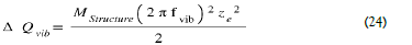
With: fvib= Vibration frequencies of the piezoelectric bridge, m = mass of this bridge, ze = maximum deflection of the bridge.
This heat, expended at the level of the piezoelectric bridge, causes its temperature increase.
As a first approximation we can say: ΔQvib = mSTRUCTURE. Cpiezo ΔT, with: Cpiezo = Specific heat capacity of the piezoelectric bridge (J Kg-1 °K-1 ), ΔT = Temperature variation (°K).
Consequently,
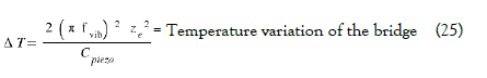
For example, for a PMN-PT piezoelectric film: Cpiezo = CPMN-PT = 310 (J Kg-1 °K-1 ),  we then obtain:
  10-3 °K which is negligible.
The expulsion of entropy from the vibrating Casimir Electrode is negligible.
So, the energy associated with the FCA force, is only used to deform the piezoelectric bridge with a WDEFCA energy and also create QF fixed charges in this structure. This energy is stored in the deformed bridge as a potential energy.
The fixed charges QF attract moving charges from the mass. When circuit 1 closed, the circuit 2 of switches MOSD is already opened (see Figure 6). The free charges Qmn, stored on the metal electrodes of face 1,passing through one of the MOSE transistors, are uniformly distributed on the Coulomb metal electrode of the same surface SP1.This metallic Coulomb’s electrode therefore has approximately a mobile charge 
The free charges Qmp, which are stored on the other grids electrode (face 2), don’t move. (Figure 5). So, grids electrode and return electrode have opposite free charge. A Coulomb’s force then appears between these two electrodes during a very short time of the order of a few tens of nanoseconds (Figure 5, 12,13,14). The position ze of appearance of this force is such that FCO =p FCA, and is numerically calculated by MATLAB (Figure 10). So, this position ze depends of the values of the interface’s zo of Casimir’s electrodes and of Coulomb’s electrodes zr We describe below the energy the cycle of the moving positions of the piezoelectric bridge.
From z0 to ze (going phase)
0< VGRIDS < VTMOSD< VTMOSE or VTMOSE < VTMOSD< VGRIDS< 0 and FCO/ FCA< p
No moving electric charge appears on the return side of the Coulomb electrode which is connected to ground by switch 2, which is ON, and isolated from the piezoelectric bridge by switch 1, which is OFF. Therefore, there is any electricals charges on this return electrode and the Coulomb force does not exist! In a cycle from z0 to ze, thus, during the displacement " going " the energy WCASIMIR is used for 3 points:
1. the deformation of the piezoelectric bridge WDEFCA,
2. the apparition of electrics charges in the of the piezoelectric bridge
3. for the energy ECA of displacement of the force FCA
4. for the creation of heat ΔQvib:
The deformation of the piezoelectric bridge is
We know that the deformation energy of an elastic system is the energy that accumulates in the solid body during its elastic deformation. Yet, the deformation energy of the piezoelectric bridge is more important than the simple displacement energy of the FCA force.
If we neglect the quantities of energy lost during the deformation ΔQvib, then a part of this work WCASIMIR is transformed partly into the elastic deformation energy of the body WDEFCA.
Let us carry out a simplified calculation to obtain an order of magnitude of this deformation energy which is spent by the Casimir force in its path from zo to ze. Consider an intermediate state during a deformation and consider that the stress σz (N.m-2 ) along the z-axis is constant during an elementary deformation dz. The total elongation in the z-direction is: εz. dz, with εz the strain along the z axis.
If dV =dx.dy.dz is the elementary volume element then the elementary work dWZ performed is:
dWZ =σz. dεz.(dx.dy.dz). Knowing that the material obeys Hooke's law with σz =Ep. εz, the total work WDEFCA of the external forces becomes, with εzm the maximum deformation at the center of the bridge, Ep Young Modulus of bridge.
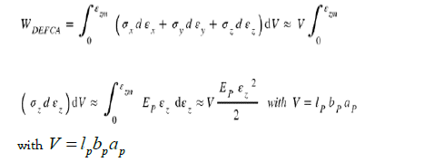
This is the approximate expression of the strain energy caused by the external force acting on this element of volume V. We have neglected the deformations and stresses along the x, and y axes.
We know that the maximum deflection of the piezoelectric bridge is Eq. (35).
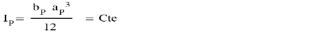
With Ip = bending moment of inertia along the z-axis of the section of this parallelepiped bridge which is:
this parallelepiped bridge which is:
Considering this arrow of the bridge subjected to a force FCA, the deformation εz can be written in first approximation by:
So, the deformation energy can be written as:
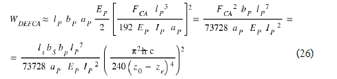
During the displacement " going " the energy WCASIMIR is used also to generates a potential energy WBridge accumulated in the capacity of this piezoelectric bridge which follows the equation: Eq. (27)
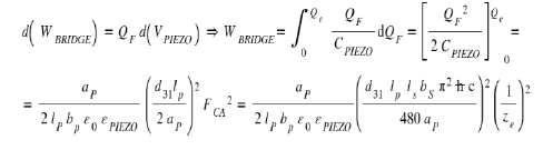
In this equation, we have d(QF)= Cpi d(Vpi ), where Cpi = electrical capacity 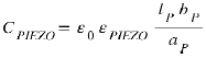 and Vpi the voltage across the piezoelectric bridge , ze the position of the very brief appearance of the Coulomb force, εpi the piezoelectric relative permittivity, lp ,bp, ap the length, width, and thickness of the bridge. With QF the naturally creating fixed charges on this piezoelectric structure.
 and Qe = -QF = the accumulated mobile charges, coming from the mass, on the surface of the “return” electrode when coulomb’s force is triggered.
So, during the phase “going” from z0 to ze the total energy Egoing = WCASIMIR is use to deform the piezoelectric bridge and to produce the electrical charges as potential energy use during the return phase.
This part Wbridge of WCASIMIR is stored in the piezoelectric bridge and is the usable energy Welectric appearing during a cycle.
Welectric is not due to any electrical energy applied, but produced by the potential energy Wbridge accumulated in the piezoelectric bridge. We have: Egoing = WCASIMIR = WDEFCA +ΔQvib/2 + Wbridge Since the elasticity conditions of the deformed piezoelectric bridge obviously apply, and we are not entering the plasticity domain, W and B are potential energies that will be used when the bridge returns to its equilibrium position, i.e., without deformation.
From ze to z0 (returning phase)
Two phases: from ze to z0 and from ze to z0. We note zc the bridge position where switch 2 switches back to ON and therefore to ground, thus cancelling the Coulomb force.
First return phase From ze to zC
As FCO/FCA ≤ p then 0 < VTPD <VGRIDS< VTNEor VTPE ≤VGRIDS ;
The sudden and ephemeral appearance of this Coulomb force is due to the fact that circuit 1, returning very quickly to the OFF state, disconnects the Coulomb electrode from the piezoelectric bridge. Shortly afterwards, circuit 2 switches back to the ON state, bringing the Coulomb electrode to ground! (See Figure 6). This cancels the FCO force.
The have already predetermined the position ze of appearance of this force such that FCO= pFCA. Note that it’s extremely small value, since it goes from 1A° for an FCO /FCA ratio = 2 to 10 A° for a ratio of 1000. (Eq 11 Figure 10).
When the equilibrium position ze is reached, the mobile’s electrical charges are:
1. on the isolated Coulomb’s electrode, the charge is constant (circuit 1 is closed and circuit 2 is opened).
 because the area of Coulomb’s electrode
  area of bridge
2. on the moving piezoelectric electrode connected to the transistor gates, the charge Qmp is time-dependent, as it depends on the bridge position over time.
Now the Coulomb force becomes
We observe that Qmp therefore FCO disappear when zs = z0, but remember that this force only exists and follows this law for the short time during which switch 2 is not closed to ground. After this time, i.e., when zs = zc, the charge on the Coulomb electrode is zero, so the Coulomb force disappears.
The energy associated with the displacements of these forces therefore takes into account that relating to the movement of the Coulomb force FCO from ze to zc (where it cancels out) and that of the displacement of the Casimir force FCA from ze to z0.
During the return phase, therefore, we have the energy induced by
 and the Coulomb’s energy

As we have seen above, during this homogenization of the mobile charges, a current and voltage peak appears for a short time. The expression of this current peak related to the homogenization of charges is Eq 9 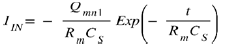 with Qmn the
preceding expression (Eq 28) of the electric charges
These cyclic current peaks induce at the terminals of the inductance
LIN a voltage peaks whose expression is:
with Qmn the
preceding expression (Eq 28) of the electric charges
These cyclic current peaks induce at the terminals of the inductance
LIN a voltage peaks whose expression is:
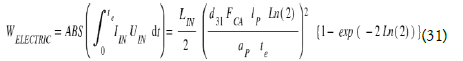
During one cycle, the only energy which is effectively used outside is associated with these power UIN IIN peaks and becomes:
From zc to z0 0 < VGRIDS ≤ VTPD < VTNE or VTPE < VTND ≤ VGRIDS < 0 When the piezoelectric bridge reaches the zc position, circuit 2 switches ON, which connects the Coulomb electrodes to ground, so FCO = 0. Only the Casimir force FCA remains.
But during the previous phase, the whole mass structure Mstructure, has acquired a speed Vstructure.
This speed gives to it a kinetic energy WCIN = ½ M structure V2 structure , so an inertia which must be spent until the stop of the structure only submit to the force FCA. This kinetic inertia induces, for the bridge, a position which can slightly exceed the starting position z0 because of the inertia.
We have WCOULOMB + WCIN +ECA = WDEFCA and:
WReturning = Wcoulomb + WCIN +ECA+Welectric±Qvib /2 = WDEFCA + Welectric +ΔQvib/2
Recall that: Wbridge = Welectric and Egoing =WCASIMIR =WDEFCA + Wbridge +ΔQvib /2
Thus, we see that in the balance Egoing - WReturning, = WCASIMIR - WCASIMIR = 0
The energy expended by the Coulomb force FCO remains weaker than the Casimir energy. This Casimir energy consumed by the deformation of the piezoelectric bridge and the creation of the electrics charges is partly restored in the form of usable electrical energy.
So, the energy WCASIMIR is conservated over a complete cycle. We do not create a new energy because the Casimir force is conservative!
Simply, the energy of Casimir is used in a different way. The ubiquitous Casimir force not only moves in a translation but more importantly deforms a piezoelectric bridge. It induces naturally a large opposing Coulomb force but of very short duration which remains of low ENERGY but of high POWER. The energy balance of a cycle therefore seems to satisfy Emmy NOTHER's theorem but it seems that we can recuperate and use a small electrical energy Welectric.
Some important remarks
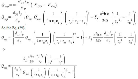
In fact, energy expended by the Coulomb force is lower than that calculated by the previous expression (Eq 29). Indeed, this WCoulomb energy is maximized for at least three reasons because:
1. The previous formula 29 presupposes that all the points along the length of the piezoelectric bridge move on a distance z0-ze, so from a position of z = zr + z0 - ze to z = zr . This consideration is wrong because the bridge is recessed at both ends.
The ends of this bridge do not move at all, only the points in x=lp/2 move on a distance z0-ze and those between the ends of bridge and the middle move on a distance shorter than z0-ze!
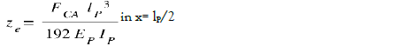
In fact (Appendix and Figure 27), for a bridge recessed in its two extremities and subjected to a force FCA in its middle, we know that the form z(x) of this bridge follows the law for 0≤ x≤ lp/2 (Appendix X Eq 36 and Figure 27)
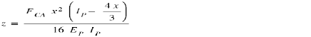

Figure 27:Bridge follows the law
The maximum zmax = ze is in x= lP/2 and is 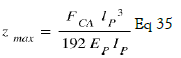 So, the calculation in equation 23 assuming that the piezoelectric bridge is completely free to move parallel to the Coulomb electrode is wrong and maximize the energy ECOULOMB.
2. Piezoelectric grid electrode and Coulomb electrode are not parallel. So, the Coulomb forces which appears at each point depend on the longitudinal position considered along the bridge and is of the form FCO(x,z) and FCA(x,z)!
3. We did not take into account these first two reasons because the fact that the Coulomb force was of greater intensity than the Casimir force but especially of a very short duration, was preponderant.
This duration depends on the stiffness and speed of the switching of the MOS transistors in depletion and enriched! An estimate of this duration is not simple because it depends on the technology used to produce these electronic components but this time should be on the order of some nanoseconds.
As the Coulombs force FCO only exists for a very short time, its power can be significant, but its energy remains low and does not exceed that of Casimir (following Figure 28).

Figure 28: Energy remains low
For these 3 reasons, the energy expended by the Coulomb force is lower than the simple equation 25 suggests and lower than the Casimir energy which induced it! There is of course conservation of energy
Note that the WCoulomb approximative expression of equation 25 depends on the term zr and decreases according to an increase in zr with a power of zr-5 ! We can therefore adapt the interval zr to minimize the energy ECoulomb!
For example, we obtain at each vibration, for an interface z0 = 200 A, zr= zo =200 A°, dimensions of the Casimir electrodes (length = 500 μm, width = 15 μm, thickness = 10 μm), dimensions of the piezoelectric bridge in PMN -PT (length = 50 μ, width = 15 μm, thickness = 10 μm), a proportionality factor p = FCO / FCA = 1000, an inductance LIN = 1.10-6 H:
1. ze = 9.46 10-09 (m) i.e., a displacement of the mobile Casimir electrode of about 105A° (Figure 10)
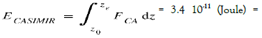 Energy of vacuum = Energy dispensed by the force of Casimir just free to move from z0 to ze
3. WDEFCA= 5.25 10-11(Joule) = deformation energy of the piezoelectric bridge, embedded at both ends, to obtain a deflection of ze at its center = energy produced by the Casimir force to deform the bridge and to give it this deflection ze. This energy is greater than ECASIMIR: WDEFCA > ECASIMIR
4. Peak current = 120 10-6 A (figure 21)
5. Voltage peak across the inductance = 0.1V (Fig 22).
6. Structure vibration frequency = 750 kHz
7. Threshold Voltage of enriched MOSE = 3.25 V (Fig 24)
8. Wbridge = 2.7 10-11 the potential energy accumulated in the piezoelectric bridge
9. Welectric = 2.7 10-11 (Joule) = Usable energy associated with current and voltage peaks.
10. WCASIMIR ≡ Wbridge + WDEFCA = 7.95 10-11 (Joule)
11. Approximative duration of one peak, tpeak ≡ 10-9s
12. Power of one peak = Welectric /tpeak ≡ 2.7 10-2 (Watt). We notice that this Welectric usable energy and the Wbridge energy are lower than the Casimir energy. This usable energy is not brought by an external source but is caused by the deformation of the piezoelectric bridge caused by the omnipresent and perpetual Casimir force, itself controlled by a Coulomb force of opposite direction.
13. ∆Qvib = heat transmitted by the vibrations of the piezoelectric bridge =7.8 10-14J is very small and negligible.
14. We notice that ΔQvib + Welectric < WCasimir which is consistent with Noether’s theorem!
15. Wcoulomb + WCIN= WCASIMIR – (ΔQvib + Welectric )= 7.95 10-11 - ( 7.8 10-14+ 2.7 10-11 ) =5.2410-11 J
Simple remark and resume
Remember that energy is defined as the “physical quantity that is conserved during any transformation of an isolated system”.
However, the system constituted by simply the MEMS device in space is not an isolated system while the system constituted by the MEMS device plus the space plus the energy vacuum seems an isolated system.
The part of the MEMS energy sensor vibrates continuously at frequencies depending of the size of the structure and operating conditions, but with an amplitude of just a few tens of Angstroms.
These vibrations should not be confused with an impossible perpetual motion, as the system can be continuously powered by the vacuum energy responsible for the Casimir force (Figure 29).


Figure 29: Initial Intermediate Situation a) â??going positionsâ?: initial Position Circuit 1 OFF, Circuit 2 ON b) â??going positionsâ?: Intermediate position Circuit 1 OFF, Circuit 2 OFF c) switching position Circuit 1 ON Circuit 2 OFF d) Returning positionsâ?: Before the moving structure reaches the position zc: Circuit 1 OFF, Circuit 2
Electronic transformation and amplification without external power supply of a periodic signal of a few millivolts into a dc voltage of a few volts
UIN . IIN power peaks lasting a few nanoseconds are present at the input of an electronic circuit without any power supply. This electronic gave encouraging simulations with a simulator SPICE. It delivers at its output an exploitable direct voltage even if it has in its input an alternating and signal of some millivolts!
The principle used to amplify and transform a weak signal without power supply derives from that of the diode bridge rectifier of Graetz or the doubler of Schenkel and Marius Latour.
The problem is that the diodes of these rectifiers are conductive only with a minimum voltage of around 0.6 V at their terminals. As the alternating signal from the vacuum energy extraction device can be weaker, it is necessary to have switches that are triggered with a lower control voltage. The principal diagram of this electronics is presented in Figure 30.

Figure 30:Principle of the one stage of the doubler without any power supply electrical diagram
In SPICE simulations, the transformer of vacuum energy describe above was assimilated to a micro transformer delivering a power UIN . IIN limited to a few nW
The MOSE N and P transistors of this rectifier circuit must have a technologically defined threshold voltage as close as possible to zero. The precision of nullity of these threshold voltages will depend on the values of alternating voltages at the terminals of the inductor LIN.
In the circuit of Figure 30, a micro transformer replaced the inductance LIN. But this inductance plays the same role as this micro transformer since it delivers a limited power UIN. IIN.
The circuit is composed of several stages, without any power supply, which rectify and amplify, on the one hand the negative parts of the weak input signal and on the other hand the positive parts.
The number of elementary stages depends on the desired DC voltage, but this DC voltage saturates with the number of stages in series (Figure 31, 32). The results obtained from SPICE simulation are shown in Figure 31.

Figure 31: SPICE simulations of voltages, current, power of the transformation electronics into a direct voltage (5.4 V) of an alternating input signal of 50 mV, frequency= 150kHz, Number of stages=14, Coupling capacities = 20 pF, stocking capacity = 10 nF

Figure 32:DC output voltages as a function of the number of elementary stages for AC input voltages of 20 mV and the other of 100 mV, Start interface = 200A °
Important points are the very low power and current consumption on the source since:
In figure 30 the power delivered by the source begin at the start with 60 nW and ends at 2.97 pW for an input current starting at 7 pA and finishing at 1pA. The component of the alternating signal 50 mv and 200 kHz is transformed in 10 ns into a negative direct voltage of Vn = -2.7 V. Likewise the component the positive alternating part is transformed into a positive direct voltage of Vp = + 2.7 V. We obtain therefore a direct voltage Vp -Vn = Vt = 5.4 V.
We need to have a high circuit output impedance of several Megaohms, so typically the input impedance of an operational amplifier.
The DC voltage obtained depends on the number of stages constituting these electronics without electrical power for transforming an AC signal of a few millivolts into a DC signal of a few volts. However, this transformation saturates with the number of floors, as shown in figure 32.
Note in Figures 32 and 33 that the DC output voltage saturates with the number of elementary stages. The optimal number of stages is of the order of 40 for an input signal of 100 mV and 20 mV. We note that this amplification saturates with a coupling capacity of 20 pF for an input signal of 10 mV and a storage capacity of 10 nF.

Figure 33: Influence of the coupling capacitance on the amplification of the input signal. Start interface = 200A °
A summary of the performance of this low “voltage doubler” device is shown in Figure 34 below

Figure 34: Summary of transformations from low alternating voltages to direct voltage frequency of 150 kHz. Start interface = 200A °
The interesting points for the presented electronics’ device are:
1. the low alternative input voltages required to obtain a continuous voltage of several volts at the output
2. the low power and current consumed by this conversion and amplification circuit on the source which in this case is only an inductor supplied by the current peaks generated by the autonomous vibrations.
3. the rapid time to reach the DC voltage (a few tens of milliseconds)
The technology used to fabricate the MOSNE and MOSPE transistors with the lowest possible threshold voltages, is CMOS on intrinsic S.O.I. The elements are isolated from each other on independent islands. This technology, represented in the following Figure 35, strongly limits the leakage currents

Figure 35: S.O.I technology for making the elements of the “doubler”
In order to minimize the size of the coupling capacitor we propose the use of titanium dioxide as insulator. His relative permittivity of the order of 100, then the size of the capacity is about 25 μm for a thickness of TiO2 = 500 A °.
Technology of realization of the current extractor device using the forces of casimir in a vacuum
For the structures presented above, the space between the two surfaces of the reflectors must be of the order of 200 A °, …. which is not technologically feasible by engraving [8,9].
Yet it seems possible, to be able to obtain this parallel space of the order of 200 A ° between Casimir reflectors, not by etching layers but by making them thermally grow!
Indeed, the SS3 and SS2 surfaces of the Casimir reflector must;
1. be metallic to conduct the mobile charges
2. insulating as stipulated by the expression of Casimir's law who established for surfaces without charges!
. This should be possible if we grow an insulator, for example Al2O3 on Alluvium film which is previously deposited. According to S.M. Sze ref, the fraction of oxide thickness "below" the initial surface is in the ratio between the molar masses of the oyde thermally formed from the oxidizable (Figure 36) [10].

Figure 36: Growth of SiO2 oxide on silicon
The molecular masses of Alumina and aluminium are MAl2O3 = 102 g/mole and MAl = 27 g/mole. We obtain an aluminium attack ratio of 27/102 = 26%, which implies that the original surface of this metal has shifted by 26% so that 74% of the alumina has grown out of the initial surface of the aluminium Regarding the technological manufacture of electronics and structure, it therefore seems preferable:
1. For electronics to choose Titanium Oxide because of its high relative permittivity εr =114 allowing to minimize the geometries required for the different capacities
2. For the Casimir structure, the choice of aluminium, because its low density increases the resonant frequency of the structure and that 74% of the Alumina Al2O3 is outside the metal, allowing to reduce the interface between Casimir electrodes.
A simple calculation shows for example that for aluminium gives: Figure 37
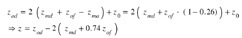

Figure 37: Distribution of thicknesses
For example, we start from an opening zod = 3 μm. We deposit a metal layer of aluminium that is etched leaving a width zmd = 1 μm on each side of the reflector. It is then possible to grow an Al2O3 alumina whose thickness is precisely adjusted, simply by considerations of time, temperature and pressure, in order to adjust the thickness necessary to obtain the desired interface z0!
For example, if z0 = 200A °, zod = 3 μm, zmd = 1 μm, then zof = 0.662 μm. So, we obtain a Casimir interface of 200 A°. The final remaining metal thickness will be zmf = 0.338 μm and will act as a conductor under the aluminium oxide.
Obviously, the growth of this metal oxide between the electrodes of the Casimir reflector modifies the composition of the dielectric present between these electrodes, therefore of the mean relative permittivity of the dielectric.
The average permittivity e0m of the dielectric is:
Steps for the realization of the structure and its electronics
We use an SOI wafer with an intrinsic silicon layer: The realisation start with voltage "doubler" is obtained by using CMOS technology with 8 ion implantations on an SOI wafer to make:
1. The sources, drains of the MOSNE, MOSND of the "doubler" and of the Coulomb force trigger circuits and of the grounding.
2. The source, drains of the MOSPE, MOSPD of the "doubler" and of the Coulomb force trigger circuits.
3. The best adjusts the zero-threshold voltage of the MOSNE of the "doubler" circuit
4. The best adjusts the zero-threshold voltage of the MOSPE of the "doubler" circuit.
5. To define the threshold voltage of the MOSNE of the circuit n°1.
6. To define the threshold voltage of the MOSPE of the circuit n°1
7. To define the threshold voltage of the MOSND of the circuit n°2
8. to define the MOSPD threshold voltage of the circuit n°2.
This electronic done, we take care of the vibrating structure of CASIMIR
9. engrave the S.O.I. silicon to the oxide to define the location of the Casimir structures (Figure 38)

Figure 38: Etching of S.O.I silicon
10. Place and engrave a protective metal film on the rear faces of the S.O.I wafer (Figure 39)

Figure 39: Engraving of the protective metal rear face of the S.O.I. silicon
11. Deposit and engrave the piezoelectric layer (Figure 40)

Figure 40: Deposition and etching of the piezoelectric layer e 61 deposition and etching of the piezoelectric layer
12. Depose and etch the metal layer of aluminium (Figure 41).

Figure 41: Metal deposit, Metal engraving etching of the piezoelectric layer
13. Plasma etching on the rear side the silicon of the Bulk and the oxide of the S.O.I wafer protected by the metal film to free the Casimir structure then very finely clean both sides (Figure 42)

Figure 42: View of the Casimir device on the rear face, engraving on the rear face of the structures.
14. Place the structure in a hermetic integrated circuit support box and carry out all the bonding necessary for the structure to function.
15. Carry out the thermal growth of aluminium oxide Al2O3 with a measurement and control of the circuit under a box. The electronic circuit should generate a signal when the interface between the Casimir electrodes becomes weak enough for the device to vibrate and then stop the oxidation. (Figure 43)

Figure 43: Adjusted growth of metal oxide under the electronic control, front view of the Casimir device
16. Create a vacuum in the hermetic box. In the case where the 2 metal electrodes of Casimir, adhere to one another, they can be separated by the application of an electrical voltage on the Coulomb’s electrodes.
Conclusion
According to this study, it would seem we can extract energy from the vacuum by the use of the Casimir force thwarted at the appropriate time by a temporary Coulomb force which makes the system enter into vibrations the structure.
I am fully aware that this concept may sound like incredible, but it does not seem to contradict thermodynamics’ law nor Emmy Noether's theorem and, mathematical calculations and simulations give encouraging results. This vibration seems to be of the same type as a stupid and illusory perpetual motion but the difference is that an energy is constantly brought to the vibrating system: that of the quantum vacuum.
This preliminary work seems to merit further study of this concept and the fabrication of a prototype would be the last judge! The dreamer would be happy to participate in this dream of a new source of energy
Appendix
A Few Reminders from RDM
Calculation of the deflection of a bridge recessed at its 2 ends
Note: We take the case of pure bending, the shear force T is such that With M the bending moment applied to the piezoelectric bridge. The Casimir force in the z axis is applied in lp /2 at the centre of the bridge. (Figure 44)

Figure 44: general appearance a) b) of the device studied, forces and applied moments, c) of the deformed bridge
As stated in all RDM books, the equation of the distorted mean line is:
We know that the radius of curvature p is
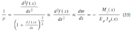
Since the bridge is parallelepiped in shape, the bending moment of inertia along the z axis of the section of this bridge is:
In the case of a beam recessed at both ends, we have a hyperstatic system.
However, we know (See works on Resistance of Materials) that at equilibrium, the sum at all points of the forces and bending moments is zero. Because of the symmetry of the system, we therefore have RAZ = RBZ and MBZ = MAz and the computational reasoning for the deformation equation is identical for 0 ≤ x ≤ lp / 2 or lp2 ≤ x ≤ lp so.
For the forces and reactions:
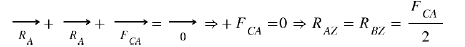
And for bending Moments:
Mx = the bending moment at a point x
MAZ = the bending moment in A
FCA = the force of Casimir applied in lp / 2 see (9)
Mz (x) = Bending moment depending on the position x on the bridge
IP (x) the bending moment of inertia of the bridge section
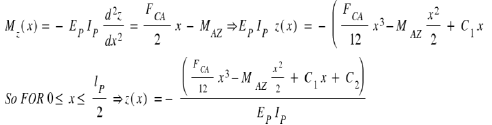
However, we have the boundary conditions which impose:
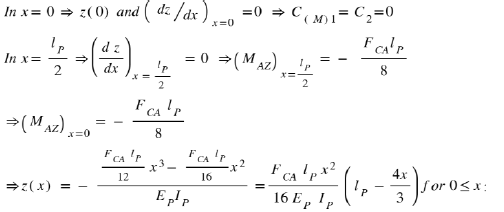
The maximum deflection in x = lp / 2 gives an arrow:
Calculation of the resonant frequency of the piezoelectric bridge
It is demonstrated (see for example: Vibrations of continuous media Jean-Louis Guyader (Hermes)) that the amplitude z (x, t) of the transverse displacement of a cross section of the beam is given by the partial differential equation, if one neglects the internal damping [7].
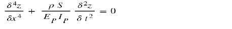
With k =  the solution of this differential equation is written in the general form:

and in the more convenient form:

Keeping into account the boundaries conditions (Figure 45):
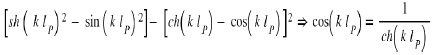

Figure 45:a / Forces, shear forces and Moments applied on the bridge. b / Variation of bending moment. c / Shape and arrow of the bridge recessed at both ends. With:  = inflection points, zmax = arrow of the bridge
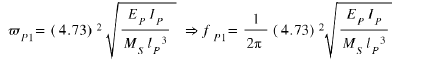
The numerical resolution (for example by the dichotomy method in this equation gives for the first 5 solutions: a1 = 4.7300; a2 = 7.8532; a3 = 10.9956; a4 = 14.1317; a5 = 17.2787
So, the first resonant frequency of the piezoelectric bridge is Eq 36
References
- Reynaud S, Lambrecht A, Genet C, et al. Quantum vacuum fluctuations. Proc Acad Sci IV Phys. 2001;9(2):1287-98.
- Casimir HB. On the attraction between two perfectly conducting plates. InProc. Kon. Ned. Akad. Wet. 1948: 51: 793).
- Lambrecht A, Reynaud S. Casimir force between metallic mirrors. Eur Phy J D. 2000; 8:309-18.
- Deriagin BV, Abrikosova II. Direct measurement of the molecular attraction of solid bodies. 1. Statement of the problem and method of measuring forces by using negative feedback. Sov Phy JETP. 1957; 3:819.
- Sangouard P. Perspective Chapter: Device, Electronic, Technology for a MEMS Which Allow the Extraction of Vacuum Energy Conform to Emmy Noether Theorem. Altern Energ Effic Eval. 2022: 30.
- Wachel JC, Bates CL. Techniques for Controlling Piping Vibration and Failures. ASME paper. 1976.
- M. BARTHES, M. Colas des Francs SOLID MECHANICAL VIBRATIONAL PHYSICS, ESTP: (Special School of Public Works).
- Parasuraman J, Summanwar A, Marty F, et al. Deep reactive ion etching of sub-micrometer trenches with ultra high aspect ratio. Micelec eng. 2014; 113: 35-9.
- Marty F, Rousseau L, Saadany B, Mercier B, et al. Advanced etching of silicon based on deep reactive ion etching for silicon high aspect ratio microstructures and three-dimensional micro-and nanostructures. Micelec j. 2005; 36(7):673-7.
- Sze SM. Semiconductor devices: physics and technology. John wiley sons; 2008.