


Design of a small scale iron and manganese removal system for Copperbelt University’s borehole water
2 Department of Civil Engineering, Copperbelt University, Kitwe, Zambia
Received: 31-Aug-2017 Accepted Date: Oct 16, 2017; Published: 24-Oct-2017, DOI: 10.4172/2591-7641.1000007
Citation: Siwila S, Chota C, Yambani K, et al. Design of a small scale iron and manganese removal system for Copperbelt University’s borehole water. J Environ Geol 2017;1(1): 24-30.
This open-access article is distributed under the terms of the Creative Commons Attribution Non-Commercial License (CC BY-NC) (http://creativecommons.org/licenses/by-nc/4.0/), which permits reuse, distribution and reproduction of the article, provided that the original work is properly cited and the reuse is restricted to noncommercial purposes. For commercial reuse, contact reprints@pulsus.com
Abstract
The study aimed at designing and performance testing of a suitable small scale Iron and Manganese removal system for Copperbelt University’s Borehole water. Materials for the filtration system were locally sourced within the Copperbelt province of Zambia. Tests were carried out on borehole water and system filtered water. The results show that the system performed relatively well on reducing Iron and Manganese from groundwater. The model constructed was a small scale version of an Up-flow filtration system. Evaluation showed performance efficiencies of 81.67% and 32% on iron and manganese removal respectively. The Up-flow design is better because water takes relatively more time to pass through the filter increasing contaminant removal capacity. The aerator tray was good but retention time for air was not sufficient and could be made better. Based on the results from the lab scale model a full scale Prototype was proposed and designed. Selecting the most applicable design largely depends on economical availability of materials, ease of construction and operation all this in relation to system efficiency. The Up-flow design in this study can be improved with respect to (i) the sedimentation tank for the settlement of oxidized iron and manganese by improving retention time of water (ii) spray nozzle to increase the surface area for aeration of water. Additionally, a substitute aerator tray with cascades to increase retention time for aeration is proposed. Furthermore, based on the model and literature review of similar designs, the sand layer depth should be at least 20 cm.
Keywords
Small scale, Iron and manganese removal system, Borehole water quality, Potable waterFacilities like deep wells where oxygen content is low, the iron and manganese- bearing water is colourless. This is because the iron and manganese are dissolved. When the water is exposed to air, the iron and manganese are oxidized and change from colourless, dissolved forms to coloured, solid forms. Oxidation of dissolved iron particles in water changes the iron to white, then to yellow and finally to red-brown solid particles that settle out of the water. Iron that does not form particles large enough to settle remains suspended [colloidal iron] and leaves the water with a red tint [1]. Manganese is usually dissolved in water, although some shallow wells contain colloidal manganese [black tint]. These sediments are responsible for the staining properties of water with high concentrations of iron and manganese [2]. These precipitates or sediments may be severe enough to plug water pipes [1]. Additionally, iron and manganese can affect the flavour and colour of food and water. According to Skimpton D [1] manganese is objectionable in water even when present in smaller concentrations than iron. There is therefore need to treat water for iron and manganese. Iron and manganese is naturally present in many aquifers throughout the world. While iron can start causing aesthetically undesirable taste and odour problems at concentrations above 0.3 ppm, concentrations of up to 3.0 ppm are often acceptable to local people; higher levels could cause people to revert to traditional unprotected sources [2] which are most times contaminated. Furthermore, according to [3,4], a big problem that frequently results from iron or manganese in water is iron or manganese bacteria. These bacteria occur in soil, shallow aquifers and some surface waters. The bacteria feed on iron and manganese in water and form red-brown [iron] or black- brown [manganese] slime in toilet tanks and can clog water systems. Technically the main problems associated with iron in water can be summed up as follows [3-6] (i) It can cause an unpleasant taste in the water; (ii) when iron precipitates out of solution it can clog up valves, small bores, pipes and other water accessories; (iii) the “brown water” is ineffective for washing; (iii) the iron can give rise to “iron bacteria [organisms that prey on iron compounds, for example frenothrix, gallionella and leptothrix]”.
There are a number of Iron and Manganese removal methods. However, these methods are dependent on the form and concentration of the iron and manganese in the water. WHO [7] mentions that, the approach to dealing with naturally occurring chemicals will vary according to the nature and source of the chemical. Key water treatment methods for iron and manganese are briefly explained below:
(i) Water Softener Iron and Manganese Removal: this method is suited for removing low concentrations of iron and manganese. It relies on the process of cat-ion exchange to remove minerals that cause hard water such as calcium, magnesium and other constituents such as iron and manganese [8]; (ii) Manganese Greensand [Iron removal filter]: this is a purple-black filter medium coated with manganese oxide and is capable of reducing iron, manganese and hydrogen sulphide from water through oxidation and filtration. Its actual removal capacities vary and depend on the characteristics of each compound [8]; (iii) Removal of iron and manganese by oxidation and microfiltration [MF]: this is especially suitable when the combination of these metals are high and variable. The results from experimentation on MF show that the oxide particles, with sizes ranging from 1.5 to 50 micrometers, can be efficiently micro filtered [9]; (iv) Aeration and Filtration Iron and Manganese removal: This method is used for removing iron in cases of concentration levels higher than 0.3 ppm but not more than 32 ppm. Aeration methods can be of two types which include a single and double tank variety.
At the Copperbelt University in Zambia, high levels of iron and manganese are suspected to be present in the borehole water. This has led to the decommissioning of two existing boreholes because of the observed damage and rusting caused to the tanks, pumps, pipe systems and related elements. This is also noticed from the slightly brown tint, when the water is collected. This has caused the institution to limit the domestic usage of water from the boreholes, and the water is now used mostly for construction purposes. Additionally, a study by WaterAid [10] shows that iron and manganese concentrations of above 1 mg/l and 0.5 mg/L respectively have been recorded on the Copperbelt province. According to WaterAid [10], increased iron and manganese concentrations are also likely in areas affected by mine drainage such as the Copperbelt province in which region the university campus lies.
To improve the quality of underground drinking water with high contents of iron and manganese the use of iron and manganese filtration systems must be considered. As highlighted above, a number of iron and manganese removal systems exist, therefore implementing the most suitable and affordable design would solve the problem by lowering iron and manganese concentrations to acceptable levels. Selecting the most appropriate design will depend on the economical availability of materials and ease of construction all this in relation to its efficiency.
This study was majorly aimed at designing and performance testing of a suitable small scale Iron and Manganese removal system for Copperbelt University’s Borehole water. Materials for the filtration system were locally sourced within the Copperbelt province. Tests were carried out on borehole water and system filtered water. A suitable iron and manganese filtration system was designed and its applicability was assessed. Necessary modifications to match material and fabrication limitations were proposed and applied. This project is among many attempts made to make the borehole water useful in many applications at the institution. The research basically looked at how to reduce concentrations of iron and manganese to allowable potable water limits and henceforth promote domestic use. Based on the results from the lab scale model a full scale Prototype was proposed and designed. The system processed water can be a good alternative source of clean and safe water to the Copperbelt University community.
Materials and Methods
Study area location
The Copperbelt University [CBU] is Zambia’s second highest learning institution and is located off Jambo Drive, in Kitwe’s Riverside area. Its coordinate location is at the intersection of longitude 028º14’25”E and latitude 012º48’20”S (Figure 1).

Figure 1: Location of Copperbelt University (Google Map, 2017)
Sampling points
The green circles in Figure 2 show the sampling points which were considered for testing and the red circles indicate the decommissioned boreholes due to the presence of high iron and manganese concentration. The boreholes are located on CBU’s main campus (Table 1 and Figure 2).

Figure 2: Sampling points (Google Earth, 2016)
TABLE 1 Borehole locations and altitudes
| Borehole | Status | Coordinates | Altitude |
|---|---|---|---|
| Borehole 1 | Active | 12° 48’ 23’’S; 28° 14’ 45’’ E | 1199 m |
| Borehole 1 | Active | 12° 48’ 24’’S; 28° 14’ 54’’ E | 1196 m |
| Borehole 3 | Decommissioned | 12° 48’ 19’’S; 28° 14’ 30’’ E | 1206 m |
| Borehole 4 | Decommissioned | 12° 48’ 28’’S; 28° 14’ 31’’ E | 1204 m |
Collection and testing of water samples
Water samples which were tested were collected from the active CBU boreholes as indicated on Figure 2 and given in Table 1. The current two active borehole are located at the new hostel construction site shown on Figure 2. The samples were tested in the CBU Environmental Engineering lab using titration and gravimetric methods with percentage error of approximately ± 2.5% and results were recorded for the following parameters: iron, manganese, pH, Total Dissolved Solids, Turbidity, Total suspended solids and E-coli. All tests were done in accordance with the Standard Methods for the Examination of Water and Wastewater [11].
Selection of iron and manganese removal system for this study
After the samples were collected and analyzed, an appropriate iron and manganese removal system was selected and designed. This was done after an intensive literature review [1-24]. An up-flow filtration system was chosen. The prototype was designed from which a model was constructed. The designed prototype drawings are shown in Appendix 2.
Model set up and testing
The model constructed was a small scale version of an up-flow filtration system. Figure 3 below gives an image and AutoCAD drawn sketch of the lab scale iron and manganese removal system [IMRS] up-flow model used during this study. Collected borehole water was passed through the filtration system. The filtrate was then comprehensively tested in the CBU’s Environmental laboratory and results recorded. The results of the filtrate tests were compared to the results of an unfiltered sample as well as WHO drinking water guidelines [23] and Zambia bureau of standards 1990 potable water standards.

Figure 3: Up-flow system model for the iron and manganese removal system photo (left) and sketch (right)
Design of the filter
In determining the size and the filtration rates of the filter bed, a desk review of relevant literature from journals, scientific reports, and academic texts on similar research projects was done [1,3-5,8,16-24]. The effective size of the filter media used was that recommended in the Danish International Development Agency [DANIDA] model [18].
The filtration minimum media depth [height] was determined using the Hudson formula to avoid breakthrough of floc as given by Das JK [18].
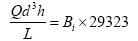
Where;
Q – Filtration rate (m3/m2/h)
L – Depth of filter bed (m)
h – Terminal head loss (m)
d - Sand size (mm)
Bi – Breakthrough index whose value ranges between 0.0004 to 0.006 depending on response to pre-treatment in the filter unit (dimensionless)
The following assumptions were made to determine the minimum sand bed depth, L:
(i)Bi = 4 × 10⁻⁴ for poor response to filtration and average degree of pretreatment and;
(ii) Terminal head loss = 0.25 m as given by Das JK [18].
From the effective sand size determined, the depth was checked against breakthrough of floc by calculating the minimum depth required.
Iron and manganese system design calculations
Aeration-sedimentation tank
Water from the hand pump outlet has to fall in a spray like manner through the spray nozzle and flows over the cascade aerator platform with granite or charcoal chips slanted towards one direction. The slant is to necessitate water flow towards the sedimentation tank. The upper side walls of the aerationsedimentation tank are to have perforation holes to allow for maximum air flow leading to rapid formation of iron precipitates which settle at the bottom of the tank. The tank was to be designed with drain outlets fitted with drain plugs at the bottom. This was to enable the tank to be emptied and thus facilitating for cleaning of the tank, about 30 minutes retention time is sufficient to significantly reduce the ferrous iron content of about 5 mg/l in the raw water. From field tests maximum water flow from the borehole was 16 l/min.
Aeration-sedimentation tank calculations
This calculation determines the volume of the aeration-sedimentation tank, (V) in order to achieve a retention time, (t) of 30 minutes having a maximum flow rate, (Q) of 16 l/min.
V = Q × t
V = 16 × 30 =480 L =0.48 m3
Hence, the required size of the aeration-sedimentation tank should be approximately 0.5 m3.
Filtration unit
Water from the aeration-sedimentation tank overflows to the filtration unit when full. The filter area was proposed to be 1 m2 [this size has been successfully used in earlier research work reviewed] [16-18]. This filter area has the capacity to accept water flow from the aeration-sedimentation tank as calculated below. The first layer to receive the water is the coarse aggregate [gravel] layer with grain size 5-8 mm as recommended from the DANIDA prototype and bed depth of 0.2 m then upward onto the second gravel layer with size 2-4 mm with bed depth 0.2 m and lastly to the third sand layer with grain size 0.8-2 mm with bed depth 0.2 m the water moves by upward flow through the layers to the outlet tap on the upper part of the filter tank thus discharging the treated [potable] water. The gravel layers at the bottom help in distribution of water through the sand filter layer, therefore, the effective filter diameter used in design is that of the sand layer, effective diameter (d) is 1.4 mm [17].
Filter capacity calculations
The flow out from the aeration-sedimentation tank is equal to the flow that enters the
Filter tank, therefore,
Qin= Qout
Qin = 16 l/min = 0.016 m3/min = 2.67 × 10⁻⁴m3/s
The formula for flow rate through the filter media which is dependent on the filter:
Area, (A) is given by Darcy’s equation [18]:
Q = k ×A × i
For vertical flow rate the hydraulic gradient, i, is 1 which gives;
Q = k×A×1 = k×A
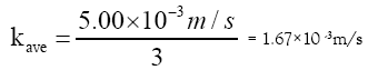
The hydraulic conductivity, k, for sand size ranging between medium and very coarse according to [18] is:
kave = 5.00 × 10⁻³ m/s
The hydraulic conductivity is divided by a safety factor of 3 due to clogging of the filter thus giving:
With the filter area, A = 1 m2 and then using Darcy’s equation to check if the suggested area can receive the flow from the aeration-sedimentation tank. We have;
Q = kave×A =1.67×103·1 = 1.67 ×10⁻³ m3/s
This flow rate is larger than the flow rate from the hand spout (2.67 x 10⁻⁴ m3/s).
Therefore, the size of the filter is adequate and thereby enabling the filter unit delivers the same amount of water as the hand pump.
Sand bed depth
The DANIDA findings [17] recommended sand bed depth of 20 cm and effective sand size of 1.4 mm. The sand bed depth was checked against breakthrough of floc through the bed by calculating the minimum depth required. The minimum depth of sand required to avoid breakthrough of floc is 13.5 cm. Hence the assumption of 20 cm depth of sand bed to avoid breakthrough of floc is adequate.
Filtration component head loss calculations
Darcy’s law was then used to calculate the head loss in the filter as follows:

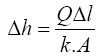
For design purposes and simplicity, the calculations were based on filter media consisting of one layer [design scenario is sand with grain size of 1.4 mm] and L being the sand bed depth. The area, (A), the flow rate, (Q), hydraulic conductivity, (k), and sand bed depth are the same as used under section 2.7.4.
With A = 1 m2, Q = 2.67 × 10⁻⁴ m3/s, k = 1.67 × 10⁻³ m3/s and L = 0.20 m the head loss is:
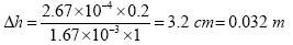
Filter volume calculations
For the effective working of the filter, a filter surface area of 1 m2 is necessary to deliver filtered water at a rate of approximately 16 l/min assuming the guidelines on head and filter sand size/depth are adhered to. Given a head loss of 0.032 m, the recommended Iron and Manganese removal system, will be able to deliver treated water as follows:
Volume, V = 0.032 m × 1 m2 = 0.032 m3
Materials for the proposed iron and manganese removal system design
The proposed iron and manganese filter system design is to be constructed using bricks produced locally. Other components needed are a dust screen and a lid to cover the tank and the filter unit respectively. The covers can be made of plastic or tarpaulin. The inside of the filter system should be water proofed to prevent water leakages. The proofing can utilize both polythene sheet and sand-cement mortar. The use of locally available material is important to ensure that the construction of the filter system is of low cost. The filter media both sand and gravel can be sourced locally. The design drawing for the proposed iron and manganese removal system is attached in Appendix 1.
Results and Discussion
Water quality analysis
The table below shows the results of the water test done on samples obtained from the active borehole at the new hostel construction site and the assessment parameters tested initially in order to confirm the claims of Iron and Manganese presence in the water (Table 2).
TABLE 2 Initial raw water quality compared to WHO and ZABS standards
| Parameters | Unit | Raw Water Sample A | Raw Water Sample B | WHO (2010) Standards | ZABS (1990) |
|---|---|---|---|---|---|
| Standard | |||||
| pH | - | 6.5 | 6.4 | 6.5 – 8.5 | 6.5 – 8.0 |
| T.D.S | mg/l | 10.6 | 6.9 | 1000 | 1000 |
| Alkalinity | mg/l | 64 | 58 | - | - |
| Fe | ppm | 3.1 | 1.3 | 0.3-1 | 0.3 |
| Mn | ppm | 0.3 | 0.1 | 0.1 | 0.1 |
| Total Coliforms | cfu/100ml | 100 | 95 | 0 | 0 |
| Faecal Coliforms | cfu/100ml | 17 | 23 | 0 | 0 |
The results obtained were a clear indication that the initial cause for concern was justified. Following these initial tests further samples were collected and tested before and after passing through the lab scale filtration system.
Water quality data analysis
Table 3 shows the concentrations of Iron and Manganese for ten samples of water collected and passed through the model of the filtration system.
TABLE 3 Water test results for Fe and Mn before and after filtration
| Sample No. | Fe Concentration before filtration | Fe Concentration after filtration | Mn Concentration before filtration | Mn Concentration after filtration |
|---|---|---|---|---|
| (ppm) | (ppm) | (ppm) | (ppm) | |
| 1 | 3.1 | 0.9 | 0.3 | 0.2 |
| 2 | 1.3 | 0.5 | 0.1 | 0.1 |
| 3 | 2.4 | 0.3 | 0.1 | 0.1 |
| 4 | 2.6 | 0.3 | 0.1 | 0.09 |
| 5 | 2.6 | 0.4 | 0.1 | 0.1 |
| 6 | 2.6 | 0.3 | 0.2 | 0.08 |
| 7 | 2 | 0.3 | 0.1 | 0.1 |
| 8 | 2.2 | 0.8 | 0.1 | 0.05 |
| 9 | 2.6 | 0.3 | 0.3 | 0.1 |
| 10 | 2.6 | 0.3 | 0.1 | 0.1 |
| Mean | 2.4 | 0.44 | 0.15 | 0.102 |
The results show that the concentrations of Iron were above the World Health Organization Standards [23] and Zambia Bureau of Standards guideline [ZABS] recommended guideline of 0.3 mg/l. However the filtration system substantially reduced the iron concentration and could be improved even more to meet the potable water standards. The concentrations of manganese were relatively in range with both ZABS and WHO standards and were relatively unchanged after filtration. The mean of the concentrations were also calculated and put in charts to help consolidate the results (Figure 4).

Figure 4: Comparison between concentration of Fe and Mn with potable water standards
Tests for other water quality parameters were carried out along aside the tests for Fe and Mn concentrations in the ten samples collected. Although not key parameters to the study, it was thought prudent to include tests for these other parameters; Alkalinity, pH and Total Dissolved Solids. The tests were carried out before the filtration in case any unexpected results following filtration could be explained by the presence and concentration of these parameters (Table 4).
TABLE 4 pH, TDS and alkalinity results for water quality tests before filtration
| No. | pH | Dissolved Solids | Alkalinity |
|---|---|---|---|
| (mg/L) | (mg/L as CaCO3) | ||
| 1 | 6.5 | 10.6 | 64 |
| 2 | 6.5 | 6.9 | 58 |
| 3 | 6.4 | 7.2 | 60 |
| 4 | 6.4 | 7.2 | 61 |
| 5 | 6.5 | 7.5 | 61 |
| 6 | 6.5 | 8.9 | 62 |
| 7 | 6.5 | 8.8 | 62 |
| 8 | 6.5 | 8.8 | 59 |
| 9 | 6.5 | 8.8 | 59 |
| 10 | 6.5 | 8.8 | 61 |
| Mean | 6.48 | 8.35 | 60.7 |
Performance evaluation of the iron and manganese removal plant [IRMS]
The following charts show the concentration of iron and manganese for each trial after filtration. The purpose of which is to obtain a graph of the overall performance of the system. The data used to create this bar chart is taken from Table 3.
The results show that while the manganese concentrations were relatively low, the filtration system showed some ability to reduce manganese concentrations as evident from trials 4 and 8. However there occurred some outlier values from trials 1, 6 and 9, these may have resulted from lab test errors or possible sample contamination (Figure 5).

Figure 5: Performance evaluation of IRMS in removing Mn
The system showed higher efficiency in terms of iron removal. As can be seen in Figure 6 each trial showed relatively high concentrations of iron removal from the water. Comparing the concentrations of Iron and Manganese before and filtration showed a substantial difference.

Figure 6: Performance evaluation of IRMS in removing Fe
The chart in Figure 7 shows the overall efficiency of the system at removing both iron and manganese in ground water at CBU. The following shows calculations used to obtain the efficiency of filtration, with figures taken from Table 3:

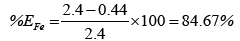
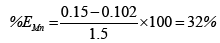

Figure 7: Performance evaluation of IRMS in removing Fe
Overall, the system performed better at removing iron than manganese. This could possibly be attributed to low concentrations of manganese making it harder to form a precipitate which is cardinal to the system performing efficiently. Hence improvement to that effect could solve the problem or maybe an additional treatment step is required for Manganese removal.
Conclusion and Recommendations
The study project aimed at designing a small scale iron and manganese filtration system for the Copperbelt University borehole water. Study conclusions were drawn and the following findings were established:
(i)Evaluation showed a performance efficiency of 81.67% and 32% of Iron and manganese respectively.
(ii)The Up-flow design is good because it offers relatively more time to filter the water than the down flow which is little bit faster.
(iii)Aerator tray good but retention time for air not sufficient (can be made better).
(iv)Locally found materials obtained from study area are suitable.
The following recommendations are suggested:
(i) The Up-flow design can be improved in with respect to:
•The sedimentation tank for the settlement of oxidized iron and manganese and to improve retention time of water.
•Spray nozzle to increase the surface area for aeration of water.
(ii) Substitute aerator tray with a cascade to increase retention time for aeration.
(iii) Based on the model and literature review of similar designs, the sand layer depth for this type of filter and application should be at least 20 cm.
(iv) Substitute charcoal chips with activated carbon whose adsorption properties are far superior to ordinary carbon materials. This will also remove odor and taste from water.
REFERENCES
- Skimpton D. Drinking Water: Iron and Manganese.
- Pontius F. Water Quality and Treatment, A Handbook of Community Water Supplies. 4th edn. American Water Works Association, McGraw-Hill; 1990.
- Barloková D, Ilavský J. Removal of Iron and Manganese from Water Using Filtration by Natural Materials. Polish J of Environ 2009;19(6):1117-22.
- Tyrrel SG. Biological removal of iron from well-hand pumps water supplies, Waterlines. London: IT publications; 1998.
- Nik N, Daud N, Nur H, et al. Ground Water Quality Improvement by using Aeration and Filtration Methods in Selangor, Malaysia. International Journal of Environmental and Ecological Engineering 2013;7(6):309-13.
- Gray NF. Water Technology - An Introduction for Environmental Scientists and Engineers. London: Arnold Publishers; 1999.
- World Health Organization. Guidelines for Drinking-water Quality First Addendum. Geneva: WHO Press; 2006.
- Lemley AT, Schwartz JJ, Wagenet LP. Water Treatment Notes, Iron and Manganese in Household Drinking Water.
- Okoniewska LK. The Removal of Manganese, Iron and Ammonium Nitrogen on Impregnated Activated Carbon. Desalination 2007;206:251-258.
- WaterAid. Groundwater Quality: Zambia, Iron and Manganese, Lusaka, Zambia; 2001.
- American Public Health Association, American Water Works Association, Water Environment Federation. Standard Methods for the Examination of Water and Wastewater; 1998.
- Hofkes EH. Small community water supplies. The Hague 1983.
- Moutain Empire Community College. Type of Filters. 2016.
- New Hampshire Department Of Enviromental Services. Ion Exchange Treatment of Drinking Water. Concord, New Hampshire: Drinking Water and Groundwater Bureau; 2006.
- World Health Organization. Manganese In Drinking-water. Geneva, Switzerland: WHO Press; 2011.
- http://www.cat.org.uk/catpubs/tipsheet.tmpl?sku=16
- http://www.lifewater.ca/drill_manual/Appendix_M.htm
- Das JK. Design of rapid gravity filter using AUTOCAD and C programming. 2007.
- Kapulu M, Lusambo E, Haankuku C. Iron Removal In Borehole Water: A Case Study Of Luapula Province. 2011.
- Ling EJ. Virginia Household Water Quality Program: Iron and Manganese in Household Water. College of Agriculture and Life Sciences, Virginia Polytechnic Institute and State University. 2011.
- Ministry of Local Govt. and Housing (MLGH). The Project for Groundwater Development in Luapula Province (Operation and Maintainance Manual for Iron Removal Plant). Lusaka: GRZ; 2008.
- Ministry of Mines Energy and Water Developmen (MMEWD). Water Quality report (High Rate Iron Removal Plant At Lukashya Clinic). Kasama: GRZ; 2012.
- http://www.csdw.org/csdw/clean-drinking-water-crisis.shtml
- http://www.total-water.com/technologies/water-filtration/microfiltration/